Novel waterproof shell for fuel cell

A fuel cell and waterproof case technology, which is applied to fuel cell components, fuel cell additives, fuel cell heat exchange, etc., can solve problems affecting water resistance and fuel cell use, and achieve increased service life and simple structure , Good cooling effect

Active Publication Date: 2017-09-15
山东汉德自动化控制设备有限公司
View PDF6 Cites 2 Cited by
  • Summary
  • Abstract
  • Description
  • Claims
  • Application Information

AI Technical Summary

Problems solved by technology

[0005] The technical problem to be solved by the present invention is that the existing fuel cell needs a heat dissipation structure, but the heat dissipation hole will affect the water resistance, and then affect the use of the fuel cell. The purpose is to provide a new type of waterproof case for the fuel cell to solve the heat dissipation and waterproof problems

Method used


Image

  • Novel waterproof shell for fuel cell

Examples


Embodiment 1

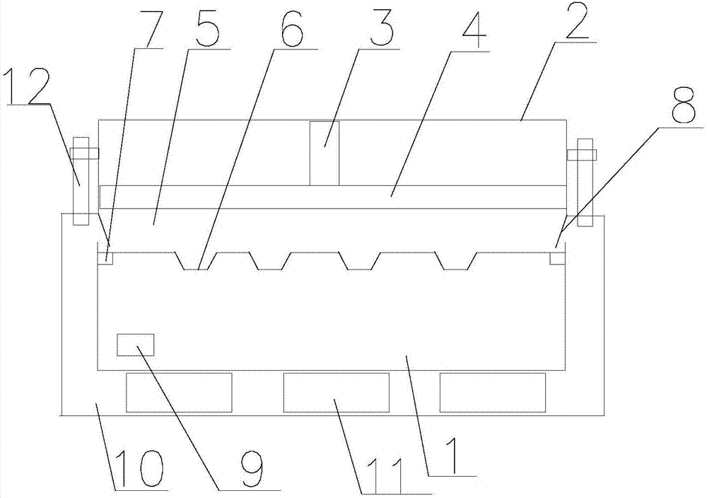
[0024] Such as figure 1 As shown, the novel waterproof case for fuel cells of the present invention includes a placement chamber 1 for accommodating fuel cells, the upper opening of the placement chamber 1 is connected with a heat dissipation chamber 2, and the heat dissipation chamber 2 is from top to bottom In turn, it includes a telescopic telescopic rod 3, an extrusion plate 4 connected to the telescopic rod 3 that can slide along the inner wall of the heat dissipation chamber 2, the lower end of the heat dissipation chamber 2 is located above the placement chamber 1, and the bottom of the heat dissipation chamber 2 has several Through hole 6, the air can flow into the placement chamber 1 from the heat dissipation chamber 2 through the through hole 6. There are several small through holes at the bottom of the placement chamber 1, and a heat dissipation channel 10 is connected to the bottom of the placement chamber 1. There are openings at both ends of the heat dissipation ...

Embodiment 2

[0026] The novel waterproof casing for fuel cells includes a placement cavity 1 for accommodating fuel cells, the top of the placement cavity 1 is open and connected with a heat dissipation cavity 2, and the heat dissipation cavity 2 includes sequentially from top to bottom A telescopic telescopic rod 3, an extruding plate 4 connected to the telescopic rod 3 and able to slide along the inner wall of the heat dissipation chamber 2, the lower end of the heat dissipation chamber 2 is located above the placement chamber 1, and the bottom of the heat dissipation chamber 2 has several through holes 6. The air can flow from the heat dissipation chamber 2 into the placement chamber 1 through the through holes 6. There are several small through holes at the bottom of the placement chamber 1, and a heat dissipation channel 10 is connected to the bottom of the placement chamber 1. The heat dissipation There are openings at both ends of the channel 10, and the openings are connected to the...

Embodiment 3

[0028] The novel waterproof casing for fuel cells includes a placement cavity 1 for accommodating fuel cells, the top of the placement cavity 1 is open and connected with a heat dissipation cavity 2, and the heat dissipation cavity 2 includes sequentially from top to bottom A telescopic telescopic rod 3, an extruding plate 4 connected to the telescopic rod 3 and able to slide along the inner wall of the heat dissipation chamber 2, the lower end of the heat dissipation chamber 2 is located above the placement chamber 1, and the bottom of the heat dissipation chamber 2 has several through holes 6. The air can flow from the heat dissipation chamber 2 into the placement chamber 1 through the through holes 6. There are several small through holes at the bottom of the placement chamber 1, and a heat dissipation channel 10 is connected to the bottom of the placement chamber 1. The heat dissipation There are openings at both ends of the channel 10, and the openings are connected to the...


PUM


Abstract

The invention discloses a novel waterproof shell for a fuel cell. The novel waterproof shell comprises a storage chamber for storing a fuel cell, wherein an opening is formed above the storage chamber and a radiating chamber is connected with the storage chamber; the radiating chamber comprises a stretching rod capable of stretching and an extruding plate connected with the stretching rod and capable of sliding along an inner wall of the radiating chamber from top to bottom in turn; the lower end of the radiating chamber is located above the storage chamber; a plurality of through holes are formed at the bottom of the radiating chamber; air can flow into the storage chamber from the radiating chamber through the through holes; a plurality of small through holes are formed at the bottom of the storage chamber; a radiating channel is jointed under the storage chamber; the openings are formed at the two ends of the radiating channel; the openings are connected with the radiating chamber; one-way slabs are connected with the two side walls of the radiating chamber; air flows into the radiating chamber through the one-way slabs from the openings of the radiating channel.

Description

technical field [0001] The invention relates to a fuel cell, in particular to a novel waterproof case for the fuel cell. Background technique [0002] After nearly 20 years of rapid development, proton exchange membrane fuel cell technology has made great progress and successfully solved many problems. However, in order to realize proton exchange membrane fuel cells, there are still problems such as low volume specific power, thermal safety problems caused by reaction heat, and high cost, which limit its commercialization in electric vehicles and other fields. [0003] Fuel cells are more and more loved and used by people because of their high energy conversion efficiency, low noise, low carbon, zero emissions, flexible and convenient use, low operating temperature, and high energy density. Fuel cells are mainly divided into five major categories: phosphate fuel cell (PAFC), proton exchange membrane fuel cell (PEMFC), alkaline fuel cell (AFC), molten carbonate fuel cell (MC...

Claims


Application Information

Patent Timeline
Patent Type & Authority Applications(China)
IPC IPC(8): H01M8/02H01M8/04007H01M2/10
CPCH01M8/02H01M8/04007H01M50/20Y02E60/10Y02E60/50
Inventor 李廷帅黄蹬峰杨鸣
Owner 山东汉德自动化控制设备有限公司
Why Eureka
Try Eureka