Bus duct power distribution device

A technology of power distribution device and busway, which is applied in the direction of semi-closed busbar device, etc., can solve the problems of complex structure of connection part, low work efficiency, large installation space, etc., so as to facilitate large-scale production and sales, and increase production efficiency , the effect of improving work efficiency

Active Publication Date: 2017-09-15
郭光伟
View PDF6 Cites 8 Cited by
  • Summary
  • Abstract
  • Description
  • Claims
  • Application Information

AI Technical Summary

Problems solved by technology

[0005] Aiming at the deficiencies in the prior art, the present invention provides a busway power distribution device to solve the problem that the existing busway power distribution device has a large volume of the busway body and a large installation space caused by the structure of the existing busway power distribution device. The manufacturing cost is high, and at the same time, the structure of the connecting part between the plug box and the main body of the busway is complicated, so the installation process is also cumbersome and time-consuming, and the work efficiency is low

Method used


Image

  • Bus duct power distribution device
  • Bus duct power distribution device
  • Bus duct power distribution device

Examples


Embodiment 1

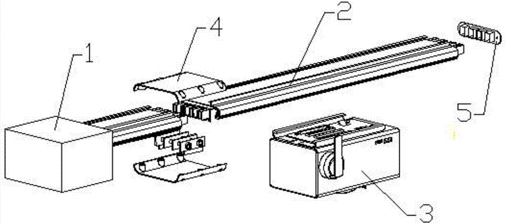
[0024] Such as Figure 1-6 and Figure 8 As shown, the present invention proposes a bus duct power distribution device, including a port box 1 for power supply, a bus duct body 2 connected to the port box 1 to transmit current, and a bus duct body connected to the bus duct body 2 to take out current. Plug-in box 3, wherein:

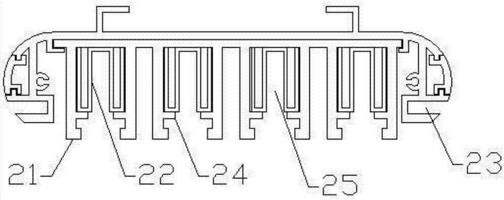
[0025] The bus duct body 2 is an inverted trough structure with an opening on the lower side, and inward card slots 23 are arranged on both side walls, and an insulating bracket 21 is arranged inside the bus duct body 2 along the direction of the channel. The top of the support 21 is connected to the inner wall of the channel. The insulating support 21 includes several conductor accommodation cavities 25 arranged side by side along the direction of the channel. In this embodiment, the number of conductor accommodation cavities 25 is four. , a symmetrical protrusion 24 is formed inward near the bottom end, and a conductor 22 with a "Π"-shaped cross secti...

Embodiment 2

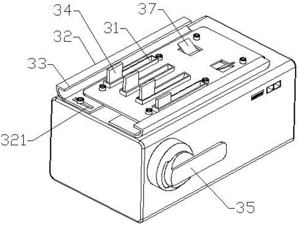
[0032] Such as Figure 7 As shown, the content of this embodiment is basically the same as that of Embodiment 1, the difference is that the transmission device 36 includes a connecting rod 364 of the vertical conductive sheet 34, the connecting rod 364 is fixedly connected with the joystick 35, and the connecting rod 364 is connected with a connection bracket 365, the connection bracket 365 is detachably connected with the conductive sheet 34 one by one, and when the joystick is rotated 35, the connecting rod 364 is driven, so that the conductive sheet 34 is directly driven to rotate through the connection bracket 365, and the conduction is completed. Snap-in or snap-off operation between the tab 34 and the conductor 22 .

Embodiment 3

[0034] Such as Figure 9 As shown, the content of this embodiment is basically the same as that of Embodiment 1, except that the conductor 22 has an inward flanging structure.


PUM


Abstract

The invention provides a bus duct power distribution device which comprises a port box used for power supply, a bus duct body connected with the port box to transmit current, and a plugging box connected to the bus duct body to connect the current out. The bus duct body is an inverted duct structure opened at the lower side. An insulating bracket is arranged inside the bus duct body along the duct way direction. The insulating bracket includes a plurality of conductor accommodating cavities arranged in parallel along the duct way direction. The plugging box includes a shell, a fixing mechanism used for being in installation connection with the bus duct body, and a conducting mechanism used for contacting a conductor to lead the current out. The bus duct body is small, occupies a small space in installation, and has a simple and beautiful appearance. As the size of the bus duct body is reduced, the production cost is lowered, large-scale production and sales are facilitated, and the production benefit is increased. The installation of the plugging box and the bus duct body is simple and convenient, and time-saving and labor-saving. The work efficiency in the process of power distribution is improved.

Description

technical field [0001] The invention relates to the field of power distribution equipment, in particular to a bus duct power distribution device. Background technique [0002] With the rapid development of urban and rural areas in modern society, the corresponding demand for power supply is also advancing by leaps and bounds. Especially in large computer rooms, large production workshops and high-rise buildings, the traditional cable power transmission method has become increasingly unable to meet the power supply requirements, so busway This power distribution device. [0003] Busway is an efficient power distribution device, which has excellent effects in rational power distribution and high-current safe transmission, especially suitable for high-rise buildings and large-scale production of electricity; busway usually includes port boxes for power supply, current transmission The bus duct body and the socket box that connects the current to the load, wherein the bus duct ...

Claims


Application Information

Patent Timeline
Patent Type & Authority Applications(China)
IPC IPC(8): H02G5/04
CPCH02G5/04
Inventor 郭光伟
Owner 郭光伟
Why Eureka
Try Eureka