Multifunctional stretcher

A stretcher car, multi-functional technology, applied in the field of medical equipment, can solve the problems of delaying rescue time, secondary injury to patients, and increasing physical burden on medical staff and patients' families, so as to avoid secondary injuries, reduce physical burden, and save rescue. effect of time

Active Publication Date: 2017-09-19
李广
View PDF12 Cites 3 Cited by
  • Summary
  • Abstract
  • Description
  • Claims
  • Application Information

AI Technical Summary

Problems solved by technology

[0004] One of the purposes of the present invention is to provide a multi-functional stretcher car to alleviate the sudden illness of high-rise building residents. When transferring through the existing stretcher, they cannot take the elevator and can only be carried downstairs fr

Method used


Image

  • Multifunctional stretcher
  • Multifunctional stretcher
  • Multifunctional stretcher

Examples


Embodiment 1

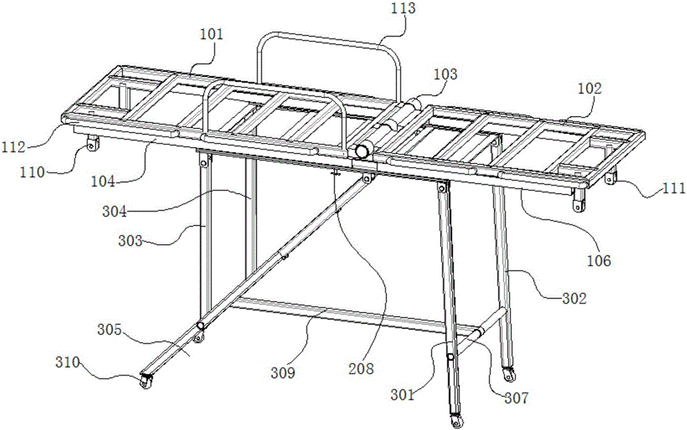
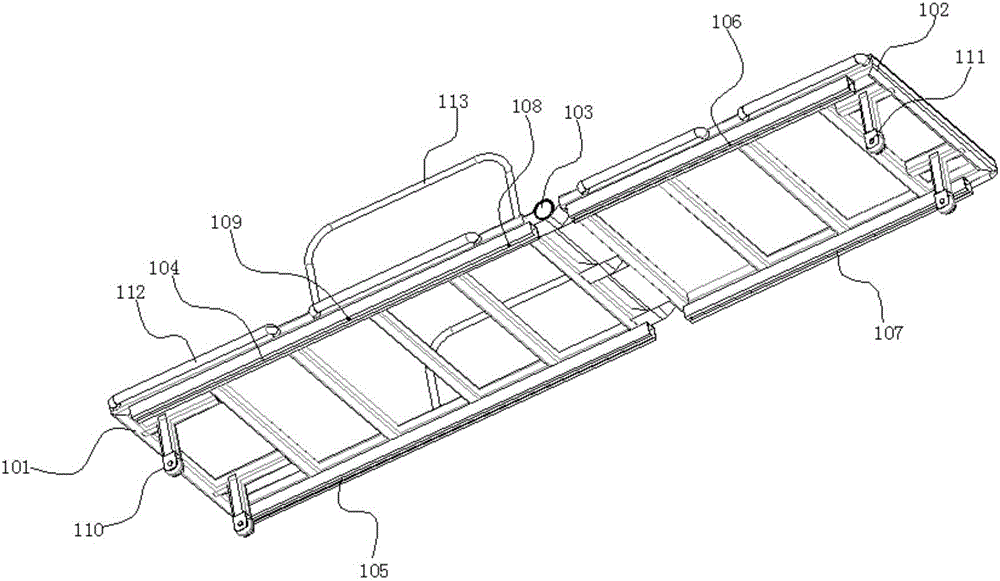
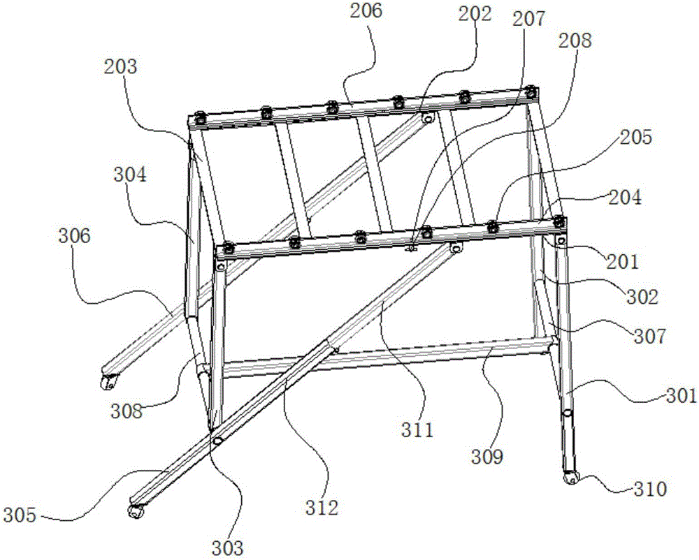
[0028] figure 1 A schematic structural view of the multifunctional stretcher provided by Embodiment 1 of the present invention; figure 2 for figure 1 The schematic diagram of the structure of the bed board shown; image 3 for figure 1 The structural schematic diagram of the supporting mechanism shown; Figure 1-3 As shown, the present embodiment provides a multifunctional stretcher cart, including a bed board and a support mechanism, the support mechanism is arranged under the bed board, and the support mechanism can slide back and forth along the length direction of the bed board; The first bed board 101 and the second bed board 102, a bed board rotating shaft 103 is arranged between the first bed board 101 and the second bed board 102, the bed board rotating shaft 103 is fixedly connected with the first bed board 101, and the bed board rotating shaft 103 is hinged with the second bed board 102 .

[0029] When the multifunctional stretcher provided by the present invent...

Embodiment 2

[0054] Figure 4 A schematic structural view of the multifunctional stretcher provided by Embodiment 2 of the present invention; Figure 5 for Figure 4 The schematic diagram of the structure of the multi-functional stretcher after entering the elevator and folding is shown. Image 6 for Figure 4 The schematic diagram of the structure of the multifunctional stretcher shown after it is fully folded; Figure 4-6 As shown, this embodiment provides a multifunctional stretcher, which is an improvement on the basis of Embodiment 1, and the technical solution described in Embodiment 1 also belongs to this embodiment, and will not be repeated here.

[0055] The difference between this embodiment and Embodiment 1 is that the multifunctional stretcher cart provided by this embodiment also includes a stretcher pad, and the stretcher pad includes a first stretcher pad 401 and a second stretcher pad 402, and the first stretcher pad 401 is arranged on the second stretcher pad. On a bed...


PUM


Abstract

The invention provides a multifunctional stretcher, and relates to the technical field of medical apparatuses and instruments. The multifunctional stretcher comprises a bed board and a supporting mechanism. The supporting mechanism is arranged below the bed board. The supporting mechanism can slide in the length direction of the bed board. The bed board comprises a first bed board body and a second bed board body which are sequentially arranged in the length direction of the bed board. A bed board rotating shaft is arranged between the first bed board body and the second bed board body. The bed board rotating shaft is fixedly connected with the first bed board body. The bed board rotating shaft is hinged to the second bed board body. The technical problem that an existing stretcher cannot go upstairs and downstairs by taking an elevator is solved, and the technical effects that under the condition of ensuring that the patient's body position is not changed, the length dimension of the multifunctional stretcher is reduced, the stretcher can be contained inside the elevator and can go upstairs and downstairs through the elevator, physical loads of medical workers and patient's relatives are relieved, the rescue time is shortened, meanwhile, effective guarantees are provided for the best salvation opportunity of the patient, and secondary injuries are avoided.

Description

technical field [0001] The invention relates to the technical field of medical devices, in particular to a multifunctional stretcher. Background technique [0002] With the development of social urbanization, there are more and more high-rise buildings, and the elevator specifications are generally small. Once a resident in a high-rise residence suddenly becomes ill, it is necessary to use a stretcher to quickly transfer the patient to an ambulance for emergency treatment, but The size of the existing stretcher is relatively large, and the patient cannot enter the elevator after lying down, and the medical staff can only carry the stretcher downstairs from the stairs. The best timing for treatment may even cause secondary harm to the patient. [0003] Therefore, those skilled in the art urgently need to develop a kind of novel stretcher, to satisfy the urgent needs of the resident of high-rise building to take elevator when carrying out emergency transfer. Contents of the...

Claims


Application Information

Patent Timeline
IPC IPC(8): A61G1/02A61G1/04A61G1/048A61G1/052
Inventor 李广金梦璐李泉盛
Owner 李广
Why Eureka
Try Eureka