
Pipe conveying device for pipe bending machining

A tube feeding and bending technology, applied in the field of electric heating tube processing equipment, to achieve a high degree of automation

Active Publication Date: 2017-09-19
安徽欧太科技有限公司
View PDF5 Cites 0 Cited by
  • Summary
  • Abstract
  • Description
  • Claims
  • Application Information

AI Technical Summary

Problems solved by technology

[0003] In the pipe bending process of large quantities of aluminum pipes, the first thing to do is to send a large number of aluminum pipes to the corresponding aluminum pipe bending equipment one by one for unified pipe bending processing, but in the existing technology, it is difficult Implemented through simple controls

Method used


Image

  • Pipe conveying device for pipe bending machining
  • Pipe conveying device for pipe bending machining
  • Pipe conveying device for pipe bending machining

Examples


Embodiment Construction

[0019] In order to make the technical means, creative features, goals and effects achieved by the present invention easy to understand, the present invention will be further elaborated below.

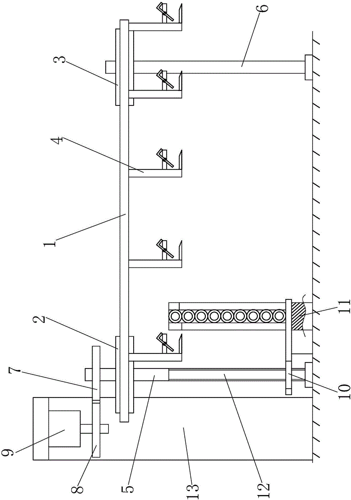
[0020] Such as Figure 1 to Figure 3 As shown, a pipe delivery device for pipe bending processing includes a main chain 1 and a left sprocket 2 and a right sprocket 3 respectively connected to the main chain 1, and the lower end of the main chain 1 is evenly arranged along the horizontal direction with aluminum The pipe clamping hand 4, the left sprocket 2 and the right sprocket 3 are connected with a left vertical rod 5 and a right vertical rod 6 respectively.

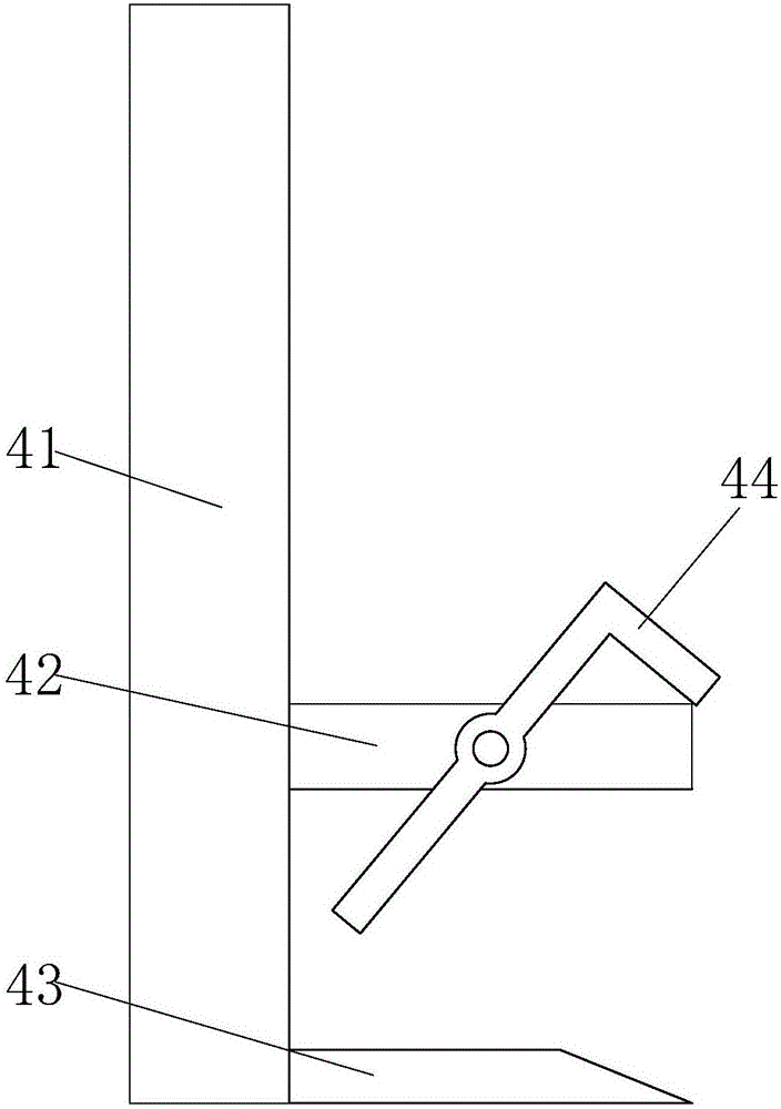
[0021] Each aluminum pipe clamping hand 4 all comprises the main column 41 that is fixedly connected with the main chain 1, and the upper limit frame 42 and the lower limit frame 43 are all welded on the main column 41, and the right ends of the lower limit frame 43 are Bevel chamfering is provided, and L-shaped protective fra...


PUM


Abstract

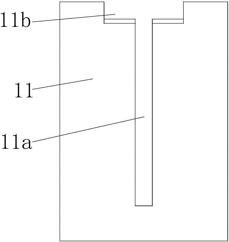
The invention relates to a pipe conveying device for pipe bending machining. The pipe conveying device comprises a main chain, a left chain wheel and a right chain wheel. Aluminum pipe clamping hands are uniformly arranged and mounted at the lower end of the main chain in the horizontal direction. The left chain wheel and the right chain wheel are connected with a left vertical rod and a right vertical rod correspondingly. A complete gear is mounted on the upper portion of the left vertical rod and engaged with an incomplete gear. The incomplete gear is connected with a motor. The lower end of the left vertical rod is fixedly connected with a lead screw. A lifting plate is mounted on the lead screw in a threaded mode. A storage frame is arranged beside the right side of the lead screw. A longitudinal groove for sliding mounting of the lifting plate in the vertical direction is formed in the storage frame. An expanding groove is formed in the upper end of the longitudinal groove. On the basis that the automatic conveying function is achieved, aluminum pipes can be further automatically lifted and supplied, and the aluminum pipes are stably grabbed through the height difference and lifting and transporting cooperativity, so that the aluminum pipes are stably conveyed in an intermittent mode, and aluminum pipe bending equipment can be matched easily to conduct pipe bending machining on batches of the aluminum pipes one by one.

Description

technical field [0001] The invention relates to an electric heating tube processing technology equipment, in particular to a tube feeding device for tube bending processing. Background technique [0002] Tubular electric heating elements (electric heating tubes) are made of metal tubes (including stainless steel and copper tubes), and spiral electric heating alloy wires (nickel-chromium, iron-chromium alloy) are uniformly distributed along the central axis of the tube, and the gaps are filled and compacted to have good insulation and heat conduction. High-performance magnesia sand, both ends of the nozzle are sealed with silica gel, this metal armored heating element can heat air, metal molds and various liquids. Generally speaking, the aluminum tube is a kind of shell that is commonly used as the metal of the electric heating tube. When the aluminum tube is used as the heating tube of the electric heating kettle, it is often necessary to make the common linear electric heat...

Claims


Application Information

Patent Timeline
Patent Type & Authority Applications(China)
IPC IPC(8): B21D43/10
CPCB21D43/006B21D43/105
Inventor 汪建文
Owner 安徽欧太科技有限公司
Learn More