Portable on-site shaft turning device

A field car and portable technology, applied in turning equipment, feeding device, thread cutting device, etc., can solve the problems of difficult disassembly, time-consuming and laborious disassembly, and inability to disassemble, to shorten the construction period, avoid disassembly work, and reduce the weight of the equipment.

Inactive Publication Date: 2017-09-19
新乡市捷瑞机床有限公司
View PDF0 Cites 5 Cited by
  • Summary
  • Abstract
  • Description
  • Claims
  • Application Information

AI Technical Summary

Problems solved by technology

The traditional repair method must remove the shaft, which is time-consuming and laborious, especially for some large shafts, long shafts, and shafts with complex assembly relationships, the disassembly will be more difficult or even impossible

Method used


Image

  • Portable on-site shaft turning device
  • Portable on-site shaft turning device
  • Portable on-site shaft turning device

Examples


Embodiment Construction

[0017] The present invention will be described in detail below in conjunction with the accompanying drawings.

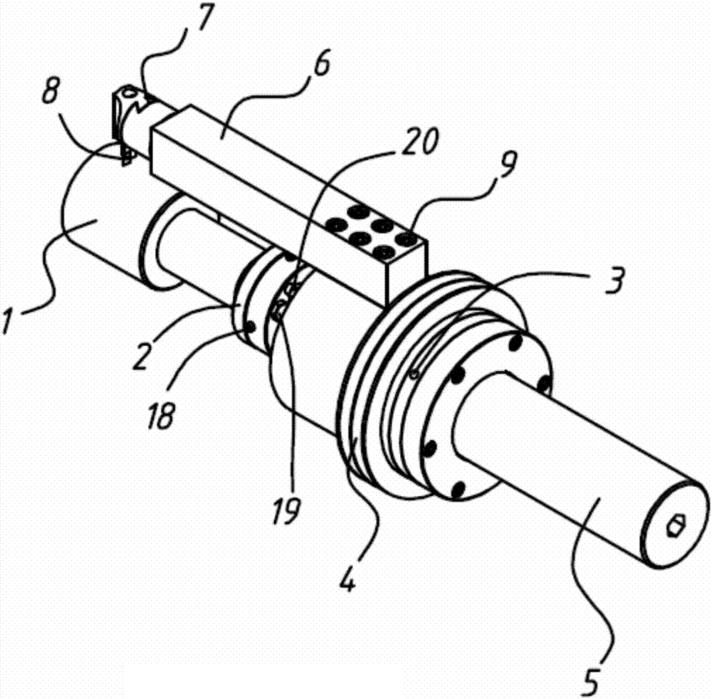
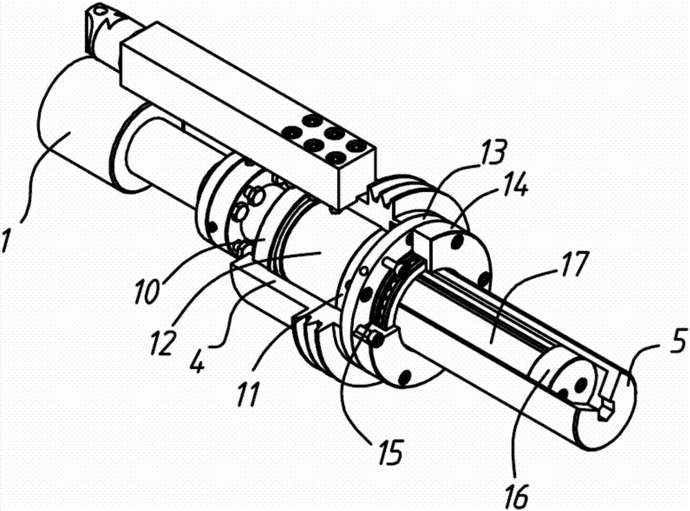
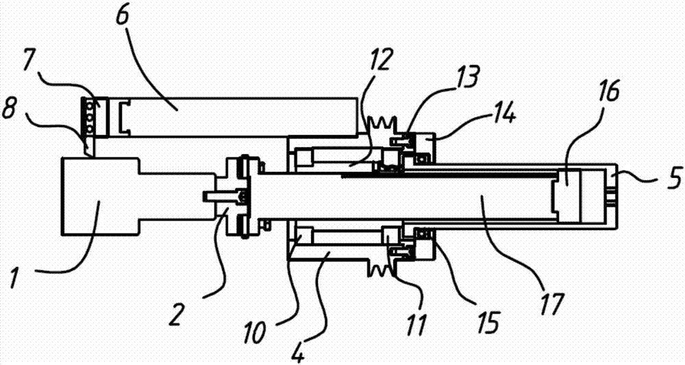
[0018] The equipment is driven by a power unit (motor, etc.) through a belt to drive the drive shaft sleeve 4 to rotate. There are bearings 10 and 11 between the drive shaft sleeve 4 and the main shaft sleeve 12. The tool bar 6 and the drive shaft sleeve 4 are fastened by bolts, so that Tool bar 6 and turning tool 8 rotate to realize circular turning motion. The main shaft 17 is fixedly connected with the workpiece 1, the main shaft sleeve 12 and the main shaft 17 are sliding fits, and there are guide keys, the end of the main shaft 17 is equipped with a feed nut 16, and the feed screw sleeve 5 is rotated by a wrench to realize the feed movement. Through the combination of the main rotation and the feed motion, the helical motion of the turning tool can be completed, and the outer circle turning can be completed. The bearing end cover 13 is connected with the feed s...


PUM


Abstract

The invention discloses a portable on-site turning shaft device, which comprises a main shaft and a rotating mechanism nested on the main shaft, and a cutter bar with a tool end is fixed on the rotating mechanism. The equipment invented by the present application is rationally designed based on the practical problems of on-site maintenance. The equipment is light in weight, easy to install and low in manufacturing cost. The equipment invented by this application adopts the method of on-site maintenance, which avoids the complex and cumbersome disassembly work during the traditional repair, so the repair period is greatly shortened, the equipment can be put into production quickly, and the economic benefit is improved. Especially for workpieces that cannot be disassembled, the equipment invented by the present application can well complete the on-site repair work, solve the technical problems of on-site repair, the equipment is easy to operate, fully operable by ordinary lathe workers, and has strong versatility.

Description

technical field [0001] The invention relates to a turning device, in particular to a portable on-site turning shaft device. Background technique [0002] During the use of equipment, many shaft parts will be worn and thread damaged due to various reasons, making it impossible to continue to use, and the worn parts and threads of the shaft must be repaired. The traditional repair method is to disassemble the shaft parts, repair the damaged part of the shaft (or other repair process) to thicken, and then use the traditional machine tool to turn the outer circle and thread to restore the original size, and then The repaired shaft is reassembled. The traditional repair method must remove the shaft, which is time-consuming and laborious. Especially for some large shafts, long shafts, and shafts with complex assembly relationships, disassembly will be more difficult or even impossible. Contents of the invention [0003] In order to solve the deficiencies of the prior art, the ...

Claims


Application Information

Patent Timeline
Patent Type & Authority Applications(China)
IPC IPC(8): B23B5/08B23Q1/70B23Q5/32B23G3/00
CPCB23B5/08B23G3/00B23Q1/70B23Q5/32
Inventor 安明生
Owner 新乡市捷瑞机床有限公司
Why Eureka
Try Eureka