Fertilizer discharging device of fertilizer applicator

The technology of a fertilization device and a fertilizer applicator is applied in the directions of fertilization device, fertilizer distributor, application, etc., which can solve the problems of small fertilization amount, time-consuming and laborious, and insufficient power of the fertilization device, so as to improve the fertilization efficiency and the fertilization quality. , the effect of high work efficiency

Inactive Publication Date: 2017-09-22
王拴柱
View PDF0 Cites 0 Cited by
  • Summary
  • Abstract
  • Description
  • Claims
  • Application Information

AI Technical Summary

Problems solved by technology

[0002] Fertilization in orchards and field fertilization has been a problem that farmers have been troubled for a long time, especially in orchards. Due to the specific conditions of the height and density of fruit trees in the orchard, if the machine is too large, due to the limited environment and space, it will If the implement is too small, it will not have enough power to get the fertilizer where it needs to be
At present, the fertilizer applicators used in farmland and orchards mainly have flat roller trough type fertilizer discharge devices. This type of fertilizer discharge box has three to four axially long grooves on the outer surface of the fertilizer discharge roller. The gap between the long grooves of the fertilizer roller sends the fertilizer to the fertilizer discharge pipe. The amount of fertilizer applied by this type of fertilizer discharge device is small and cannot reach the amount of fertilizer required by the orchard. To achieve the required amount of fertilizer, it is necessary to repeatedly apply two to three times It is time-consuming and labor-intensive to spread the fertilizer. Moreover, for powdery fertilizer or fertilizer with higher humidity, such as bacterial fertilizer, it is easy to accumulate fertilizer in the long groove of the fertilizer roller, which will further affect the effect of fertilization.

Method used


Image

  • Fertilizer discharging device of fertilizer applicator

Examples


Embodiment Construction

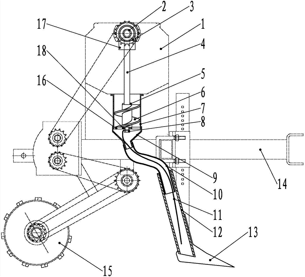
[0012] Below in conjunction with accompanying drawing and specific embodiment the fertilizer discharge device of fertilizer applicator of the present invention is further described:

[0013] Accompanying drawing is the structural representation of the fertilizer discharge device of the fertilizer applicator of the present invention. Among the figure, the frame connecting rod 14 of the fertilizer applicator can be connected with agricultural machinery such as tractors, the top of the frame connecting rod 14 is provided with a fertilizer box 1, and the following of the frame connecting rod 14 is provided with a plowshare 13 and a walking wheel 15, and the walking wheel 15 It is arranged behind the plowshare 13, and a drive shaft 2 is set above the fertilizer box 1. The drive shaft 2 is provided with a reverse gear box 17. The fertilizer discharge box 7 is fixed on the bottom surface of the fertilizer box 1, and an auger is arranged in the fertilizer discharge box 7. 6. The botto...


PUM


Abstract

The invention discloses a fertilizer discharge device for a fertilizer applicator, which comprises a fertilizer box, a fertilizer discharge box and a fertilization pipe. A transmission shaft is arranged above the fertilizer box, and an inverted gear box is arranged on the transmission shaft. The fertilizer discharge box is fixed on the inverted On the bottom surface of the fertilizer box below the gear box, an auger is arranged in the fertilizer discharge box, and a support seat is provided on the bottom surface of the fertilizer discharge box. The support seat and the inner wall of the fertilizer discharge box are connected by ribs, and the auger is fixed on the auger shaft. The upper end is connected with the output gear in the reverse gear box, the lower end of the auger shaft is connected to the support seat, the lower end of the fertilizer discharge box is connected with a fertilization pipe, the bottom end of the auger shaft is fixed with a wire rope, and the other end of the wire rope extends to Fertilizer tube. The fertilization device has a large amount of fertilizer, and one operation can meet the fertilization requirements of the orchard. Moreover, the device can apply various fertilizers, especially for powdery fertilizers and fertilizers with high humidity. The fertilization process is unblocked and the fertilization efficiency can be improved. Reach 10 times the efficiency of artificial fertilization.

Description

technical field [0001] The invention relates to an agricultural implement, and more specifically relates to a fertilizer discharge device of a fertilizer applicator. Background technique [0002] Fertilization in orchards and field fertilization has been a problem that farmers have been troubled for a long time, especially in orchards. Due to the specific conditions of the height and density of fruit trees in the orchard, if the machine is too large, due to the limited environment and space, it will If the implement is too small, it will not have enough power to apply fertilizer to the desired location. At present, the fertilizer applicators used in farmland and orchards mainly have flat roller trough type fertilizer discharge devices. This type of fertilizer discharge box has three to four axially long grooves on the outer surface of the fertilizer discharge roller. The gap between the long grooves of the fertilizer roller sends the fertilizer to the fertilizer discharge p...

Claims


Application Information

Patent Timeline
Patent Type & Authority Applications(China)
IPC IPC(8): A01C15/16A01C15/12
CPCA01C15/16A01C15/12
Inventor 王拴柱
Owner 王拴柱
Why Eureka
Try Eureka