
Rotary cutter for acetabulum

A rotary knife and acetabular technology, applied in the field of acetabular rotary knife, can solve the problems of high manufacturing cost, short tool life, complex structure, etc., and achieve the effect of low manufacturing cost, extended service life and simple structure

Pending Publication Date: 2017-09-22
崔健
View PDF12 Cites 2 Cited by
  • Summary
  • Abstract
  • Description
  • Claims
  • Application Information

AI Technical Summary

Problems solved by technology

[0008] The object of the present invention is to provide an acetabular rotary cutter, which is used to solve the problems of short tool life, complicated structure and high manufacturing cost in existing bone socket milling cutters

Method used


Image

  • Rotary cutter for acetabulum
  • Rotary cutter for acetabulum
  • Rotary cutter for acetabulum

Examples


Embodiment 1

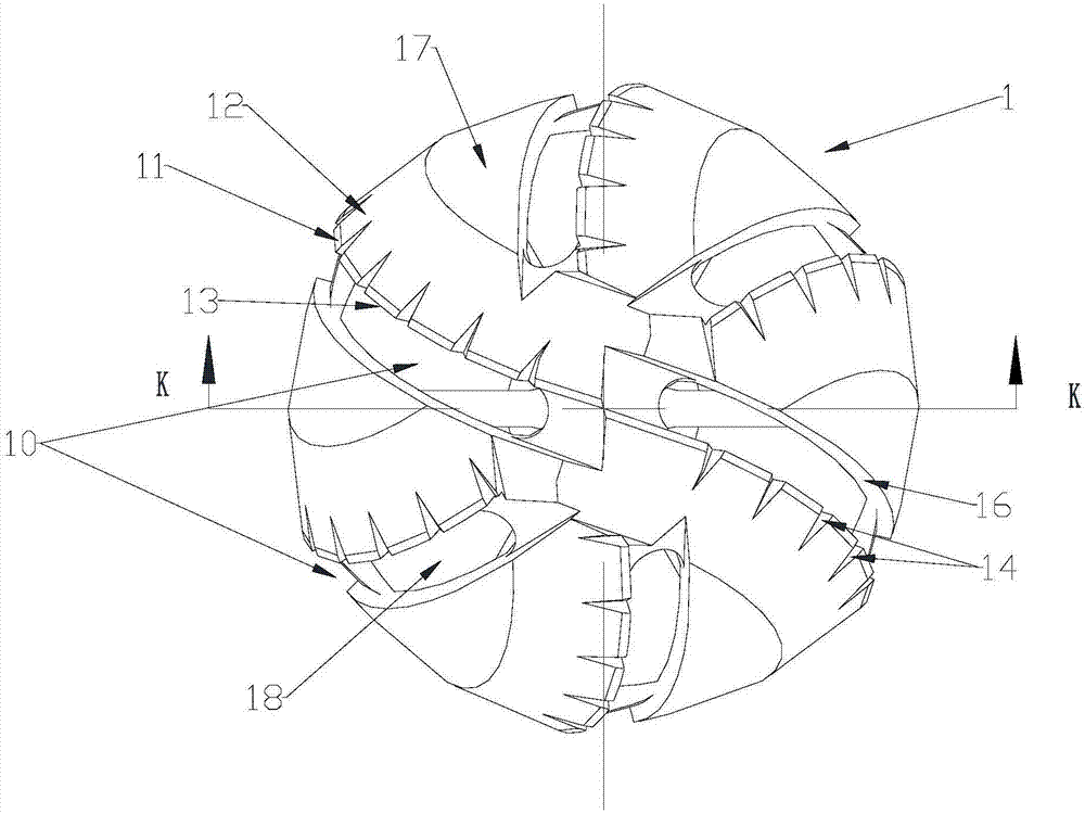
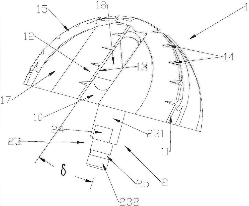
[0034] Such as figure 1 As shown, the acetabular rotary knife includes a hemispherical shell 1 and a bracket 2. The acetabular rotary knife of the present invention greatly prolongs the service life of the acetabular rotary knife by optimizing the parameters of the cutting edge 13. In addition, the acetabular rotary knife of the present invention The knife also has the advantages of simple structure and low manufacturing cost.

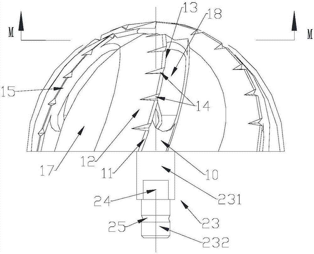
[0035] Such as figure 2 , 3, 6, 7, 9, and 10, the hemispherical shell 1 is a hemispherical shell 1 with a cavity 19 inside the lower port, and the connection between the apex of the hemispherical shell 1 sphere and the center of the hemispherical shell 1 The line is the axis of rotation, and the hemispherical shell 1 rotates around the axis of rotation when it rotates. Three pairs of grooves 10 are evenly arranged around the vertex on the spherical surface, and of course four pairs, five pairs or more grooves 10 can be arranged as required, and the...

Embodiment 2

[0038] The difference between this embodiment and Embodiment 1 is that in this embodiment, the rake angle α is constant during the process of extending downward along the rear side 15 of the groove 10, and the value range of the rake angle α is 3°-45°. °, the first relief angle β also remains constant during the downward extension, and the value range of the first relief angle β is 6°-12°. The second relief angle γ is also constant during the downward extension, and the value range of the second relief angle γ is 15°-25°.


PUM

PropertyMeasurementUnit
Widthaaaaaaaaaa

Abstract

The invention relates to a rotary cutter for acetabulum. The rotary cutter for the acetabulum comprises a hemispherical shell and a support connected to the lower end port of the hemispherical shell; the connecting line from the vertex of the sphere of the hemispherical shell to the spherical center of the hemispherical shell is a rotary axis when the hemispherical shell rotates, and at least three pairs of grooves are evenly formed in the position, around the vertex of the sphere, on the sphere; spiral lines between the vertex of the sphere and the edge of the sphere extend downwards to the edge of the sphere, a pair of grooves extend upwards to the vertex of the sphere along the corresponding spiral lines, and spiral included angles are formed between the grooves and the rotary axis; the rear side surfaces of the grooves intersect with the sphere to form cutting blades, the rotary cutter for the acetabulum is provided with a rear cutter face and a subsidiary rear cutter face, multiple notches which intersect with the cutting blades and extend to the subsidiary rear cutter face are evenly arranged on the rear cutter face, a penetration groove extending downwards along the corresponding spiral line of the groove is formed in each groove, and the height of the rear cutter face is larger than that of a cutter heel. The rotary cutter for the acetabulum has the advantages that the service life is long, the structure is simple and the production cost is low.

Description

technical field [0001] The invention relates to the field of milling cutters for bone sockets, in particular to an acetabular rotary cutter. Background technique [0002] A reamer or osteotomy cutter is a device used to remove tissue and bone from the body, specifically acetabular reamers and reamers designed to remove tissue and bone from the acetabular socket in preparation for implantation of a hip prosthetic cup. bone cutter. Typically, an acetabular reamer or osteotomy tool is constructed with a continuous partial hemisphere that is ideal for shaping the cavity to fit the prosthetic cup. Prosthetic cups implanted in the acetabulum typically have a curved outer surface, and rotating osteotomy knives use many blades with sharpened, lightly guarded blades on a hemispherical rotating head. [0003] US Patent Publication No. US 4,131,116 discloses an osteotomy cutter with a hemispherical cutting head. The tool has a number of radial grooves extending from the outer surfac...

Claims


Application Information

Patent Timeline
IPC IPC(8): A61B17/16
CPCA61B17/1659A61B17/1666
Inventor 崔健
Owner 崔健
Learn More