Eureka AIR delivers breakthrough ideas for toughest innovation challenges, trusted by R&D personnel around the world.

Cutting device of plate making machine

A technology of cutting device and plate making machine, which is applied in the direction of manufacturing tools, forming/shaping machines, special forming/shaping machines, etc., can solve the problems of time-consuming and labor-consuming, low production efficiency, poor cutting performance, etc., and achieve beneficial Long-term use, improved safety and good cutting performance

Active Publication Date: 2017-09-22
安徽温禾新材料科技股份有限公司
View PDF6 Cites 2 Cited by
  • Summary
  • Abstract
  • Description
  • Claims
  • Application Information

AI Technical Summary

Problems solved by technology

[0002] The so-called board machine cutting device is one of the main equipment used for board machine cutting. For people's love for wood products, many daily necessities and toys in life are continuously made of wood, and the shapes of wood products are various. In the same way, there are many notches on many wood products now, one is for aesthetics, and the other is for ventilation to increase air flow. Many wood products are now manually slotted, which is time-consuming and labor-intensive. The efficiency is low, and the sawdust is left unattended, and there are many dust particles in the air, which affects the health of the staff, and the accumulated sawdust is easy to be squeezed when cutting the groove. In order to improve the production efficiency, a flat cutting hob can be used, which has high sensitivity and stable performance. , has a good promotion prospect
[0003] However, the existing board-making machine cutting devices have many types, but they have a single function, and can only be used for simple board-making cutting, and cannot be cut and formed at one time. The slotting of many wood products needs to be done manually, which is time-consuming and labor-intensive, and the production efficiency is low. , and the accumulated sawdust is easy to squeeze when cutting the groove, its cutting performance is poor, and the quality of the cut wood is poor, and there are few types of cut wood, which reduces the utilization rate of the cutting device

Method used


Image

  • Cutting device of plate making machine
  • Cutting device of plate making machine
  • Cutting device of plate making machine

Examples


Embodiment Construction

[0019] The following will clearly and completely describe the technical solutions in the embodiments of the present invention with reference to the accompanying drawings in the embodiments of the present invention. Obviously, the described embodiments are only some, not all, embodiments of the present invention. Based on the embodiments of the present invention, all other embodiments obtained by persons of ordinary skill in the art without making creative efforts belong to the protection scope of the present invention.

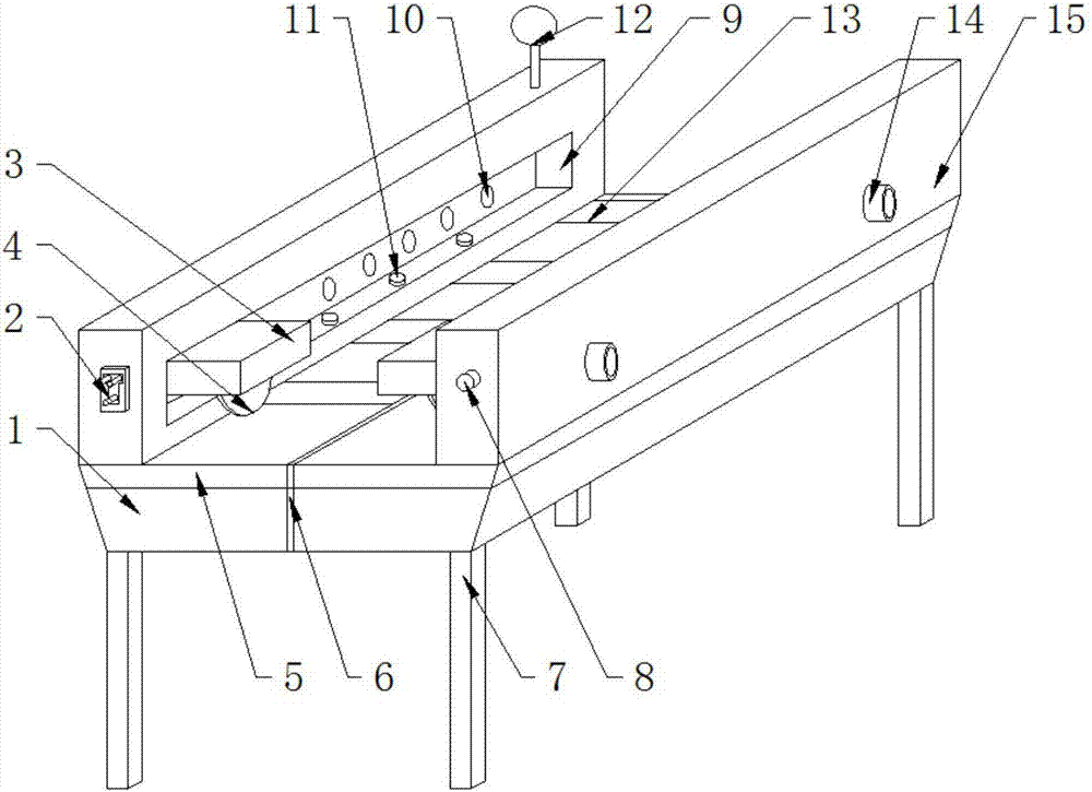
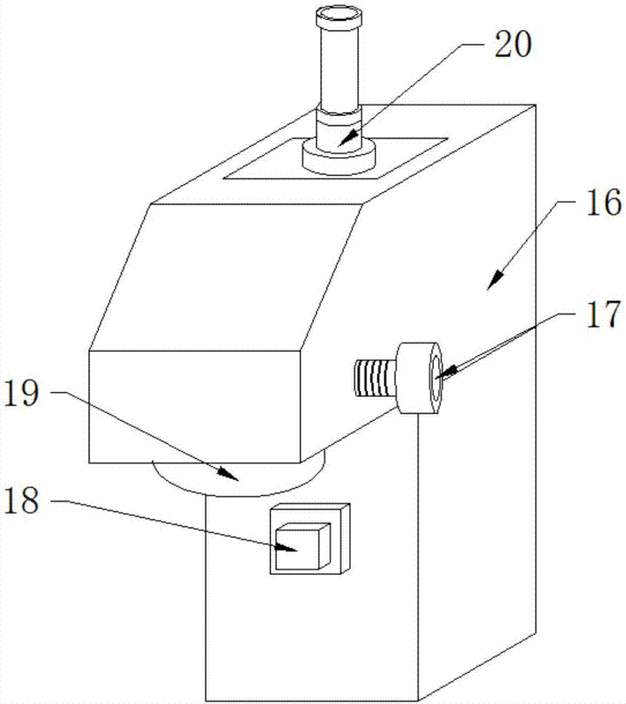
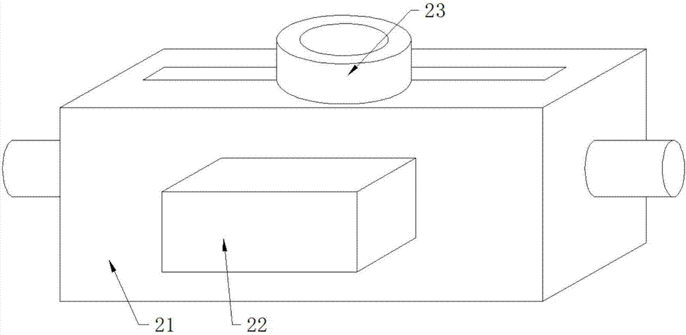
[0020] see Figure 1-3 , the present invention provides a technical solution: a cutting device for a plate making machine, including a device body 1, the device body 1 is composed of a fixed baffle 15 arranged at the top of the device body 1 and a force-bearing tripod 7 at the bottom, And the stressed tripod 7 and the fixed baffle 15 are tightly welded with the device body 1, the side of the fixed baffle 15 is provided with a symmetrical rolling shaft 14, and ...


PUM


Abstract

The invention discloses a cutting device of a plate making machine. The cutting device comprises a device body; the device body is composed of fixing baffles and stress foot frames, wherein the fixing baffles are arranged at the top end of the device body, and the stress foot frames are arranged at the bottom of the device body; the stress foot frames and the fixing baffles are tightly welded to the device body; symmetric rolling shafts are arranged on the side surfaces of the fixing baffles and are embedded in the fixing baffles; starting switches are arranged on one sides of the rolling shafts and are electrically connected to the rolling shafts; and guide rail grooves are formed in the fixing baffles. According to the cutting device, due to the fact that an end surface cutting hob and a plane cutting hob are combined, the cutting device can be used for complex plate making and cutting, cutting forming can be completed at a time, the problem that a lot of wooden products need to be grooved manually can be solved, time can be saved, labor force can be saved, and in addition, speed reducers are used so that the cutting speed can be conveniently controlled din the cutting process.

Description

technical field [0001] The invention relates to the technical field of cutting devices, in particular to a cutting device for a board making machine. Background technique [0002] The so-called board machine cutting device is one of the main equipment used for board machine cutting. For people's love for wood products, many daily necessities and toys in life are continuously made of wood, and the shapes of wood products are various. In the same way, there are many notches on many wood products now, one is for aesthetics, and the other is for ventilation to increase air flow. Many wood products are now manually slotted, which is time-consuming and labor-intensive. The efficiency is low, and the sawdust is left unattended, and there are many dust particles in the air, which affects the health of the staff, and the accumulated sawdust is easy to be squeezed when cutting the groove. In order to improve the production efficiency, a flat cutting hob can be used, which has high sen...

Claims


Application Information

Patent Timeline
Patent Type & Authority Applications(China)
IPC IPC(8): B27C5/02B27C5/06
CPCB27C5/02B27C5/06
Inventor 温中苏
Owner 安徽温禾新材料科技股份有限公司
Why Eureka
Eureka Blog
Learn More