High pressure ejection unlocking device

A technology of unlocking device and high voltage, applied in the direction of launch/drag transmission, launch system, transportation and packaging, etc., can solve the problem of difficulty in unlocking the ejection device, and achieve the effect of improving stability, reliability and stability

Active Publication Date: 2019-08-09
CHINA ACAD OF AEROSPACE AERODYNAMICS
View PDF4 Cites 0 Cited by
  • Summary
  • Abstract
  • Description
  • Claims
  • Application Information

AI Technical Summary

Problems solved by technology

[0004] The purpose of the present invention is to overcome the above-mentioned deficiencies in the prior art, and provide a high-pressure ejection unlocking device, which solves the problem that the ejection device is difficult to unlock when ejecting with a higher ejection force, ensures that the ejection mechanism can still be quickly unlocked during high-pressure ejection, and improves ejection. The reliability of the organization's operation

Method used


Image

  • High pressure ejection unlocking device
  • High pressure ejection unlocking device
  • High pressure ejection unlocking device

Examples


Embodiment Construction

[0029] Below in conjunction with accompanying drawing and specific embodiment the present invention is described in further detail:

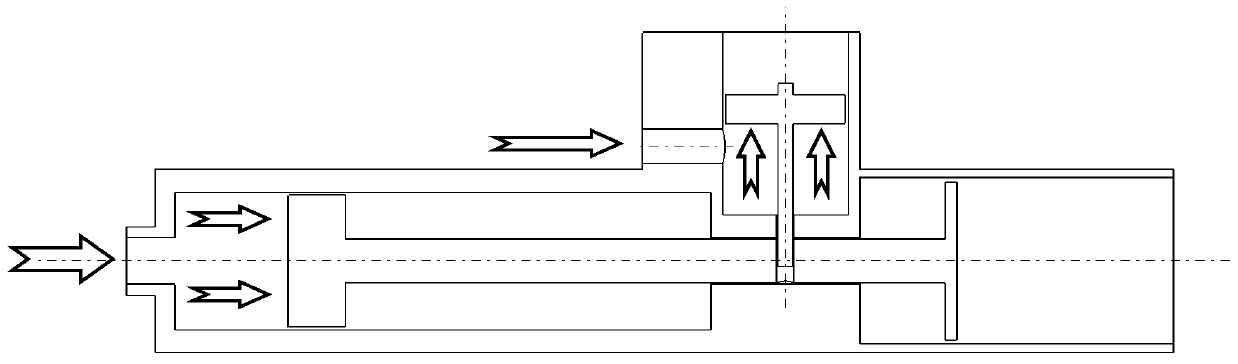
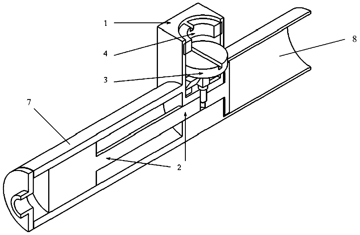
[0030] Such as figure 2 Shown is a schematic diagram of the structure of the ejection unlocking device of the present invention (locked state), the high-pressure ejection unlocking device of the present invention includes an unlocking cylinder 1, a small piston rod 3, a large piston rod 2, a main cylinder 7 and an ejection barrel 8, a hollow nut, and 4 gears Plate 5 and gas path platform 6. Wherein the small piston rod 3 is arranged in the unlocking cylinder 1, the large piston rod 2 is arranged in the main cylinder 7 and the catapult 8, the large piston rod ejection surface 2-2 is located in the catapult 8, and the main cylinder 7 and the catapult 8 are connected with the unlocking cylinder 7. The cylinder 1 is connected, and the master cylinder 7 and the catapult 8 are located on both sides of the unlock cylinder 1 respectively. The baffle ...


PUM


Abstract

The invention relates to a high-pressure catapult unlocking device. The high-pressure catapult unlocking device comprises an unlocking air cylinder, a small piston rod, a large piston rod, blocking plates, air channel tables, a main air cylinder and a catapulting barrel, wherein the small piston rod is placed in the unlocking air cylinder; the cylinder surface of the small piston rod is matched with the cylinder surface in the unlocking air cylinder; the blocking plates are fixedly connected to the small piston rod; the number of the blocking plates is the same as that of the air channel tables; the plane of each blocking plate can be in surface sealing contact with the plane of the corresponding air channel table; when the small piston rod moves outwards, the situation that the small piston rod is vertically collided to the air channel tables can be avoided by the bevels of the blocking plates, and colliding can be further avoided by the chamfer of each air channel table; a rod body of the small piston rod penetrates through a through hole in the bottom of the unlocking air cylinder to be inserted in a large piston rod hole of the large piston rod; and a catapulted object is put in the catapulting barrel to be in contact with the catapulting surface of the large piston rod. According to the high-pressure catapult unlocking device disclosed by the invention, the problem that when high catapulting force is utilized for catapulting, the catapulting device is difficult to unlock is solved, so that the situation that during high-pressure catapulting, a catapulting mechanism can also be quickly unlocked can be guaranteed, and the operating reliability of the catapulting mechanism is improved.

Description

technical field [0001] The invention relates to mechanical design and wind tunnel test, in particular to a high-voltage ejection unlocking device test mechanism, which belongs to the fields of mechanical design and aerospace engineering. Background technique [0002] The ejection device is a commonly used object ejection separation mechanism, and its power source includes compressed air, spring and electromagnetic force. In practical application, in order to make the ejected object have sufficient separation speed and ejection distance, the device needs to be locked before ejection, and then unlocked when the ejection force accumulates to a certain value, so as to realize effective ejection. The movement principle of the existing ejection device is as follows: insert the bottom end of the small piston rod used for unlocking as a pull pin into the piston rod of the ejection cylinder, lock the ejection mechanism, and apply an outward force on the small piston when unlocking to...

Claims


Application Information

Patent Timeline
Patent Type & Authority Patents(China)
IPC IPC(8): B64F1/06B64G1/00
CPCB64F1/06B64G1/002
Inventor 薛飞刘畅杨益农朱剑
Owner CHINA ACAD OF AEROSPACE AERODYNAMICS
Why Eureka
Try Eureka