Anode electroplating device

An anode device, anode technology, applied in the direction of electrodes, current conduction devices, etc., can solve the problems of product scorch, coating thickness, affecting product quality and other problems

Inactive Publication Date: 2017-09-22
BOARDTEK ELECTRONICS CORP
View PDF5 Cites 5 Cited by
  • Summary
  • Abstract
  • Description
  • Claims
  • Application Information

AI Technical Summary

Problems solved by technology

[0005] This phenomenon will cause the product to have a thick coating at a place with a high current density, whereas the product will have a thin coating at a place with a low current density; not only will the quality of the product (especially sub-products) be seriously affected due to the uneven coating on the surface of the product, In some cases, excessive current

Method used


Image

  • Anode electroplating device
  • Anode electroplating device
  • Anode electroplating device

Examples


Embodiment Construction

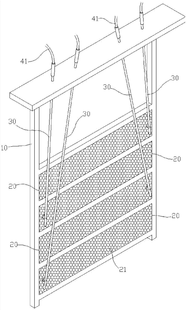
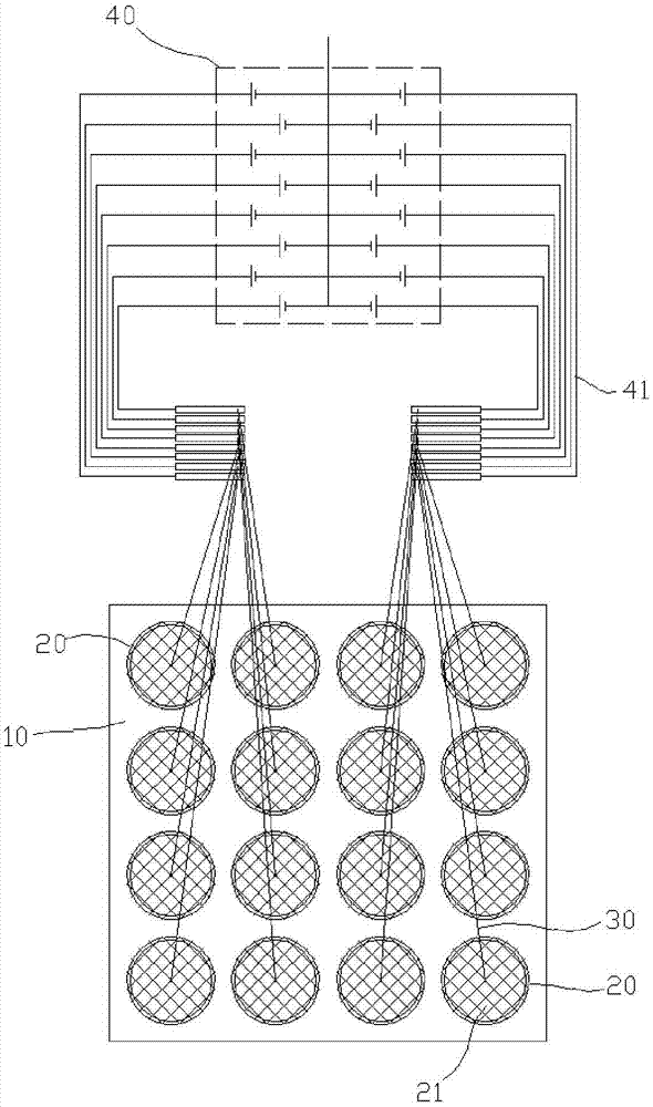
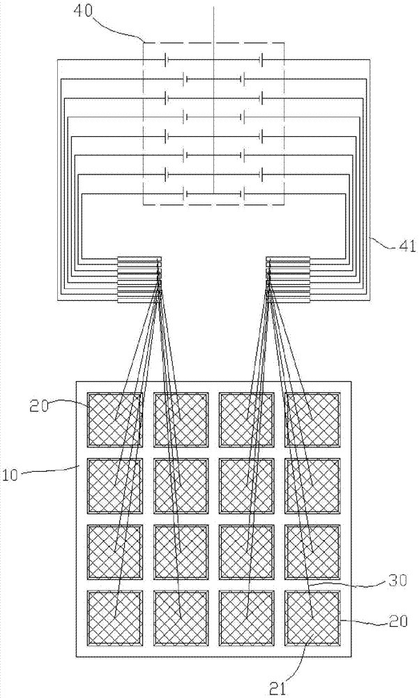
[0036] The present invention mainly provides an electroplating anode device that can adjust the power distribution state according to the product shape or product hanging configuration, such as figure 1 As shown, the electroplating anode device of the present invention has a frame body 10, and a plurality of anode parts 20; wherein, each of the anode parts 20 is arranged on the frame body 10 in a mutually insulated state, and a plurality of conductive parts 30 are also provided. They are respectively electrically connected to each of the anode parts 20 .

[0037] In principle, for the electroplating anode device of the present invention, in practical application, the paired electroplating anode devices can be placed on both sides of the electroplating tank relative to the cathode, and the products to be electroplated are hung on the cathode, so that they are respectively on the anode end. Under the state of inputting current to the cathode terminal, the electroplating solution...


PUM


Abstract

The electroplating anode device of the present invention is mainly designed with a plurality of anode parts which can be used to control the conduction of the circuit respectively on a frame, so that any or any number of anode parts can be energized in the electroplating tank. Generate different power line distribution states; especially, when the appearance of the product to be electroplated or the hanging configuration type is changed, it only needs to simply switch the current supply circuit to generate the corresponding power line distribution state, so that it can be relatively more It is a positive and reliable means to ensure the quality of product electroplating.

Description

technical field [0001] The invention is related to the electroplating system, and mainly provides an electroplating anode device for the electroplating system that can adjust the power distribution state according to the shape of the product or the configuration of the hanging configuration of the product. Background technique [0002] As we all know, "electroplating" is a method of coating a layer of film on an object by electrolytic reduction reaction. The machinery and equipment used in it vary with different electroplating products. Electrode rods of varying numbers are designed in the electroplating area as anodes, so that metal ions can be dissociated in the electroplating solution, and the workpiece to be plated is usually designed as a cathode. [0003] During the electroplating operation, the voltage is input to the anode and the cathode respectively, so that the electroplating solution will precipitate metal ions due to the electrolytic reaction, and these metal io...

Claims


Application Information

Patent Timeline
IPC IPC(8): C25D17/12
CPCC25D17/12C25D17/007
Inventor 郑文锋萧舜昌罗焕星许吉昌孙尚培
Owner BOARDTEK ELECTRONICS CORP
Why Eureka
Try Eureka