Pavement crack disease detection system and method

A technology of pavement cracks and detection methods, which is applied in the direction of roads, roads, road repairs, etc., can solve the problems of improving detection efficiency and detection accuracy, affecting normal driving safety, and not being able to perform real-time detection, so as to achieve automatic interpretation and automatic intelligence Effect of treatment

Active Publication Date: 2017-09-22
TECH TRANSFER CENT CO LTD NANJING UNIV OF SCI & TECH
View PDF20 Cites 5 Cited by
  • Summary
  • Abstract
  • Description
  • Claims
  • Application Information

AI Technical Summary

Problems solved by technology

The main problem of using manual direct observation and interpretation is that real-time detection cannot be carried out, which affects normal driving safety during the detection process, and the detection efficiency and detection accuracy need to be improved
[0003] The crack identification method based on the crack two-dimensional image is based on the difference between the illumination characteristics of cracks under certain lighting conditions and the road surface itself, but this is not the essential characteristic of cracks, because the principle of two-dimensional image sensing cannot be completely overcome , the interference factors such as lighting conditions, shadows, road oil, sundries and other interference factors in the acquisition process, the information obtained only through the crack two-dimensional image cannot extract the complete crack information, and cannot reflect the depth characteristics of the crack
[0004] Recently, a three-dimensional visualization measurement system using GNSS (Global Navigation Satellite System) has also been produced. This system collects data through connecting satellite systems and transmits it to dedicated equipment for reading and writing. It can achieve more accurate measurement results, but its price Expensive, not suitable for general large-scale use

Method used


Image

  • Pavement crack disease detection system and method
  • Pavement crack disease detection system and method
  • Pavement crack disease detection system and method

Examples


Embodiment Construction

[0022] In order to better understand the technical content of the present invention, specific embodiments are given together with the attached drawings for description as follows.

[0023] Aspects of the invention are described in this disclosure with reference to the accompanying drawings, in which a number of illustrated embodiments are shown. The disclosed embodiments of the invention are not necessarily intended to include all aspects of the invention. It should be appreciated that the various concepts and embodiments described above, as well as those described in more detail below, can be implemented in any of numerous ways, since the concepts and embodiments disclosed herein are not limited to any implementation. In addition, some aspects of the present disclosure may be used alone or in any suitable combination with other aspects of the present disclosure.

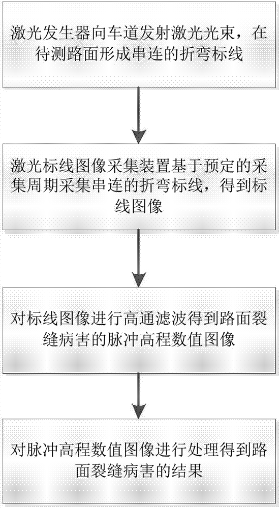
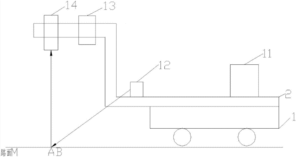
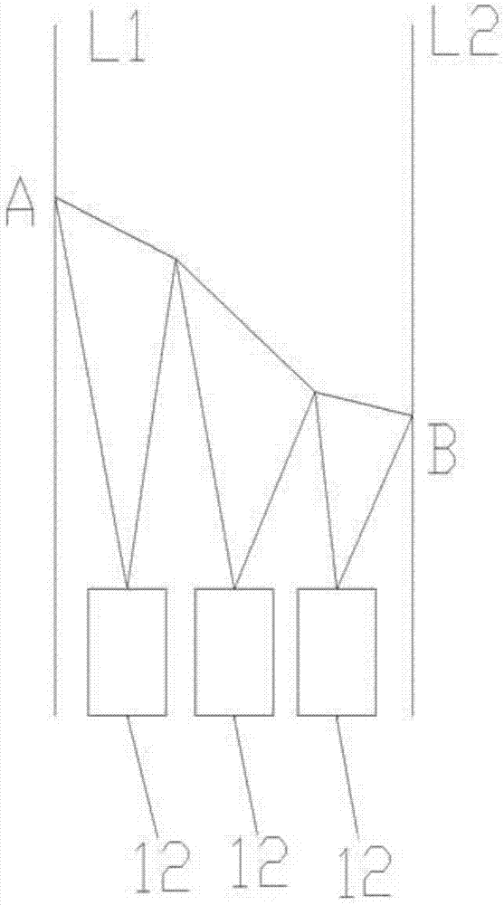
[0024] combine figure 1 , figure 2 , image 3 As shown, according to an embodiment of the present invention...


PUM


Abstract

The invention provides a pavement crack disease detection method. The method comprises the following steps: laser generators emitting laser beams to lanes to form a series-connected bending marking line on the to-be-detected pavement; an image acquisition device, based on a preset collection period, acquiring a series-connected bending marking line image to obtain marking line images; carrying out high-pass filtering on the marking line images to obtain pulse elevation numerical images of the pavement crack disease; and processing the pulse elevation numerical images to obtain a result of the pavement crack disease. According to the pavement crack disease detection method, automatic and intelligent treatment of the pavement disease is realized, the problem that pseudo-cracks generated by water traces and oil traces, existing in an image photography method generally adopted at home and abroad, is solved, so that the automatic interpretation of complex grey-scale patterns is realized, relevant information of the pavement disease is directly obtained through processing, manual interpretation is not needed, and safety is guaranteed.

Description

technical field [0001] The invention relates to the field of pavement detection systems, in particular to a method and system for measuring cracks and pits in the pavement of roads or other similar structures. Background technique [0002] At present, in the field of pavement crack detection, the damage of crack damage mainly adopts manual direct observation and interpretation and the crack recognition method of crack two-dimensional image by computer. The main problem of using manual direct observation and interpretation is that real-time detection cannot be carried out, and normal driving safety is affected during the detection process, and the detection efficiency and detection accuracy need to be improved. [0003] The crack identification method based on the crack two-dimensional image is based on the difference between the illumination characteristics of cracks under certain lighting conditions and the road surface itself, but this is not the essential characteristic o...

Claims


Application Information

Patent Timeline
Patent Type & Authority Applications(China)
IPC IPC(8): E01C23/01
CPCE01C23/01
Inventor 贺安之贺宁贺斌
Owner TECH TRANSFER CENT CO LTD NANJING UNIV OF SCI & TECH
Why Eureka
Try Eureka