
Rotatably-welding rivet and riveting method thereof

A technology of spin welding and rivets, applied in rivets and other directions, can solve the problems of prolonging production time, increasing the structural deformation of thin-walled plates or related components, and being unable to ensure sealing, etc., and achieves the effect of low cost

Inactive Publication Date: 2017-09-22
柳州博纳汽车科技有限公司
View PDF6 Cites 7 Cited by
  • Summary
  • Abstract
  • Description
  • Claims
  • Application Information

AI Technical Summary

Problems solved by technology

[0002] In many installed equipment and equipment, it is necessary to install and fasten the thin-walled plates or related components to the design position, and to ensure the firmness of the installation. The usual method is to use riveting nuts to fasten the thin-walled plates or related components. Riveting with corresponding components, however, before riveting, holes must be pre-drilled at the riveting position, so that the riveting nut can pass through the plate and related components for riveting, if no pre-drilling is made, riveting cannot be performed
[0003] When the thin-walled sheet or related components are made of lightweight metal plates, the pre-opening before riveting not only increases the production process and prolongs the production time, but also increases the risk of structural deformation of the thin-walled sheet or related components; If the hole is pre-drilled, the seal cannot be guaranteed

Method used


Image

  • Rotatably-welding rivet and riveting method thereof
  • Rotatably-welding rivet and riveting method thereof
  • Rotatably-welding rivet and riveting method thereof

Examples


Embodiment Construction

[0033] In order to enable those skilled in the art to better understand the technical solutions of the present application, the present invention will be further described in detail below in conjunction with the accompanying drawings and embodiments.

[0034] The orientation terms such as up, down, left, right, front and rear in this application document are established based on the positional relationship shown in the drawings. If the drawings are different, the corresponding positional relationship may also change accordingly, so this should not be understood as limiting the scope of protection.

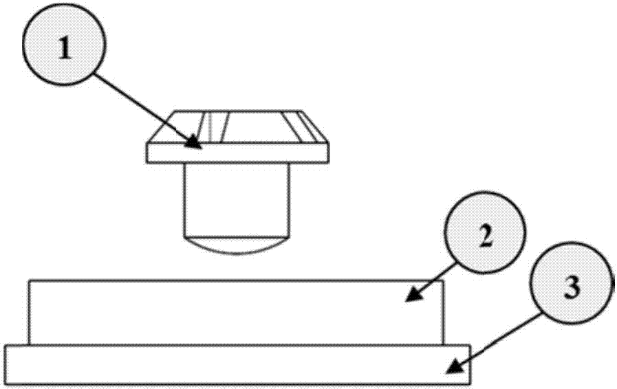
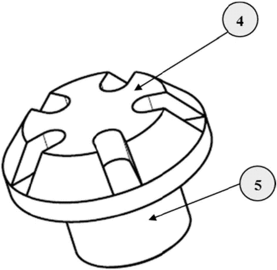
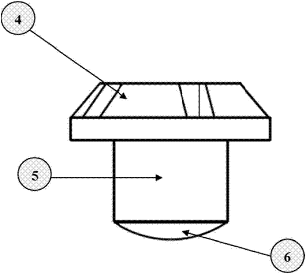
[0035] This embodiment describes a rotary welding rivet, hereinafter referred to as rivet 1, which is mainly used for the connection of light metal plates, such as aluminum plates, aluminum alloy plates, magnesium aluminum alloy plates and other light metal plates and steel plates, such as figure 1 The connection of light metal sheet 2 and steel sheet 3 is shown.

[0036] Such as ...


PUM


Abstract

The invention relates to a rotatably-welding rivet. The rivet comprises a rivet head, a rivet body and a rivet tail part. The rivet head and the rivet tail part are arranged at the two ends of the rivet body correspondingly and share the same axis with the rivet body. The bottom surface of the rivet head is provided with a material-storing groove. The material-storing groove is arranged on the rivet body in an encircling mode. The rivet is connected with a driving head of a special rivet installation device through the rivet head. The rivet installation device drives the rivet to rotate in a high speed through the rivet head. The rivet tail part is used for piercing a light metal plate and connected with the contacting area of a steel plate in a fused and welded mode. According to the rotatably-welding rivet, connection between the dissimilar metal plate and the steel plate is achieved, piercing the steel plate is not needed, the sealed waterproofing can be achieved, cutting is avoided in the riveting process, scrap materials are not generated, special heating treatment and surface treatment are not needed to be conducted on the rivet, and the cost is relatively low.

Description

technical field [0001] The invention relates to a connecting piece, in particular to a rotary welding rivet. Background technique [0002] In many installed equipment and equipment, it is necessary to install and fasten the thin-walled plates or related components to the design position, and to ensure the firmness of the installation. The usual method is to use riveting nuts to fasten the thin-walled plates or related components. Riveting with corresponding components, however, before riveting, holes must be pre-drilled at the riveting position so that the riveting nut can pass through the plate and related components for riveting. If no pre-drilling is made, riveting cannot be performed. [0003] When the thin-walled sheet or related components are made of lightweight metal plates, the pre-opening before riveting not only increases the production process and prolongs the production time, but also increases the risk of structural deformation of the thin-walled sheet or relat...

Claims


Application Information

Patent Timeline
Patent Type & Authority Applications(China)
IPC IPC(8): F16B19/06B21J15/12
CPCF16B19/06B21J15/12
Inventor 张斌
Owner 柳州博纳汽车科技有限公司
Learn More