Swing frame mechanism of dynamic calibration equipment

A dynamic calibration and equipment technology, applied in the direction of transmission, mechanical equipment, belt/chain/gear, etc., can solve the problems of unfavorable conduction, belt tension change, belt stretching, etc., and achieve stable conduction, easy operation, and extended The effect of using time

Inactive Publication Date: 2017-09-22
航天南洋(浙江)科技有限公司
View PDF5 Cites 0 Cited by
  • Summary
  • Abstract
  • Description
  • Claims
  • Application Information

AI Technical Summary

Problems solved by technology

However, this type of transmission equipment has defects: after the belt is used for a period of time, the belt will be stretched, which will cause the tension of the belt to change, which makes the transmission unfavorable, so it is necessary to carry out regular inspections of the belt transmission equipment. Adjustment

Method used


Image

  • Swing frame mechanism of dynamic calibration equipment

Examples


Embodiment Construction

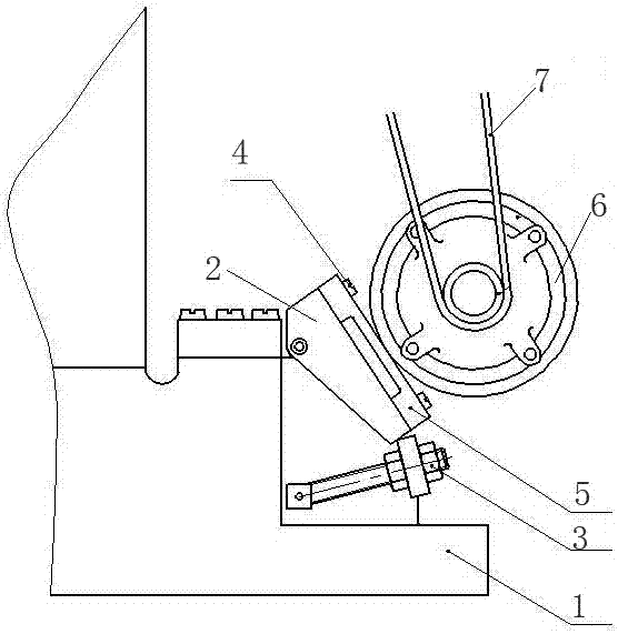
[0010] Combine below figure 1 Specific examples:

[0011] The swing frame mechanism for dynamic calibration equipment includes a frame body 1. A swing frame 2 is provided at the upper end of the frame body 1. One end of the swing frame 2 is hingedly arranged on the frame body 1, and the other end of the swing frame 2 is connected with The adjusting nut 3 is connected; the swing frame 2 is provided with an adjusting plate 5 through the fixing screw 4, the adjusting plate 5 can be slid on the swing frame through the fixing screw, the adjusting plate 5 is connected with the motor 6, and the output end of the motor 6 is connected There is belt 7; when the belt needs to adjust the tension, first loosen the fixing screw, adjust the adjustment nut, make the swing frame swing downward, adjust to the specified position, lock the adjustment nut, then fix the fastening screw, and adjust the motor to The desired location.

[0012] Preferably, the adjusting nut is hingedly arranged on the fra...


PUM


Abstract

The invention belongs to the technical field of belt transmission tools, and particularly relates to a swing frame mechanism of dynamic calibration equipment. The swing frame mechanism of the dynamic calibration equipment comprises a frame body. A swing frame is arranged at the upper end of the frame body. One end of the swing frame is arranged on the frame body in a hinged joint manner. An adjusting plate is connected with a motor. The output end of the motor is connected with a belt. When the belt needs to adjust tension force, fixed screws are firstly loosened, an adjusting nut is adjusted, the swing frame is made to swing downwards and adjusted to the designated spot, the adjusting nut is locked, then a fastening screw is fixed, and the motor is adjusted to the needed position. The swing frame mechanism has the beneficial effects that the tension force of the belt can be adjusted regularly, the belt can keep the proper tension force, transmission is more stable, the structure is simple, and operation is convenient.

Description

Technical field [0001] The invention belongs to the technical field of belt conduction appliances, and particularly relates to a swing frame mechanism for dynamic calibration equipment. Background technique [0002] At present, in equipment that uses belts for conduction, one end of the belt is connected to the output end of the motor, and the other end is connected to the equipment that needs to be driven. The rotation of the motor drives the rotation of the equipment. However, this kind of transmission equipment method has disadvantages: after the belt is used for a period of time, the belt will be stretched, which will cause the tension of the belt to change, which makes the transmission unfavorable. Therefore, it is necessary to regularly conduct the belt transmission equipment. Adjustment. Summary of the invention [0003] The purpose of the present invention is to solve the above-mentioned technical problems and provide a dynamic that can periodically adjust the tension of...

Claims


Application Information

Patent Timeline
Patent Type & Authority Applications(China)
IPC IPC(8): F16H7/14
CPCF16H7/14
Inventor 李贝田忠涛郭进成
Owner 航天南洋(浙江)科技有限公司
Why Eureka
Try Eureka