flow regulator unit

A flow regulator, regulating core technology, applied in flow control, control/regulation systems, instruments, etc., can solve problems such as noise, and achieve the effect of reducing the installation length

Active Publication Date: 2019-11-19
NEOPERL
View PDF7 Cites 0 Cited by
  • Summary
  • Abstract
  • Description
  • Claims
  • Application Information

AI Technical Summary

Problems solved by technology

The use of a flow regulator unit of the type mentioned at the outset in the current hydraulic block of the heating control unit leads to the formation of undesired, noticeable noises

Method used


Image

  • flow regulator unit
  • flow regulator unit
  • flow regulator unit

Examples


Embodiment Construction

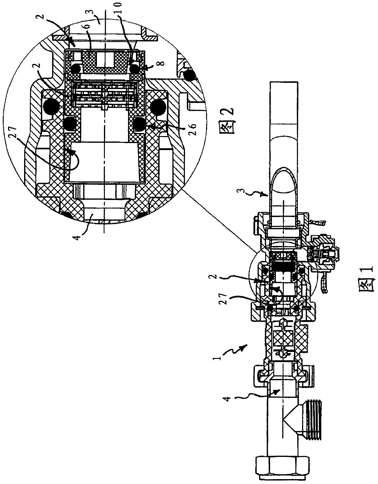
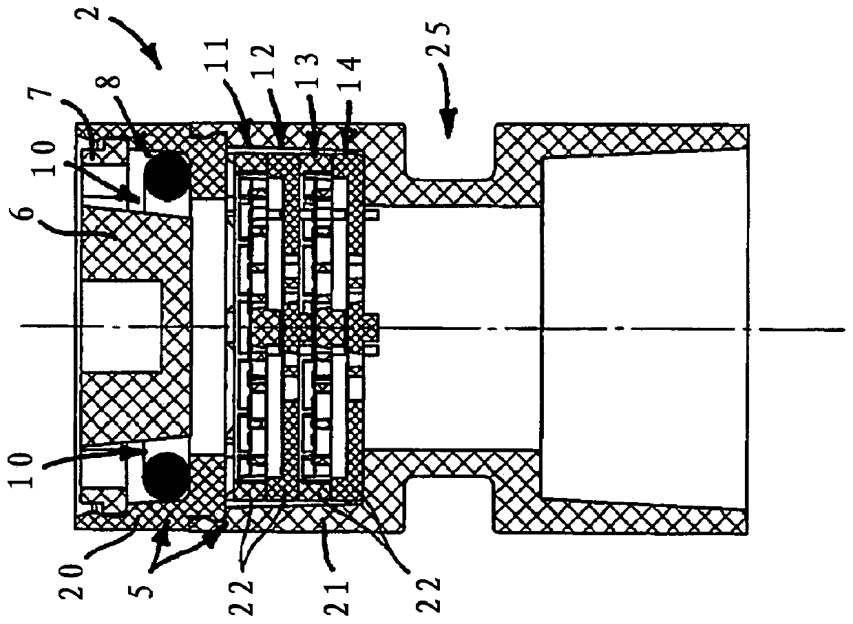
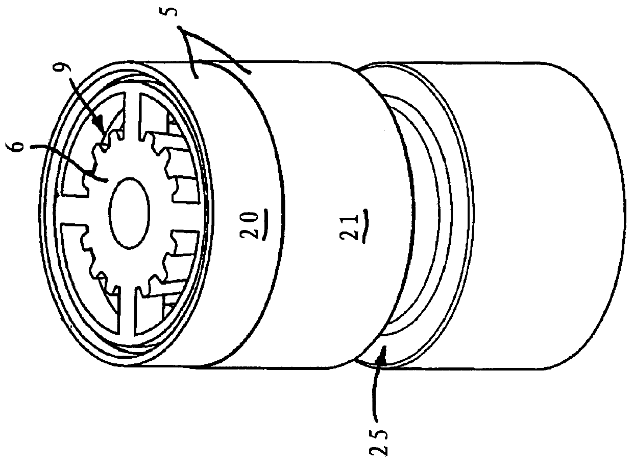
[0032] exist figure 1 and figure 2The hydraulic block 1 of the heating control device is shown in . A water line is led through the hydraulic block 1 , which is divided into an inflow-side pipe section 3 and an outflow-side pipe section 4 by the plugged-in flow regulator unit 2 . The flow regulator unit 2 has a built-in housing 5 , which is plugged at a distance before the water intake point between the inflow-side pipe section 3 and the outflow-side pipe section 4 of the sanitary water pipe. In the built-in housing 5 of the flow regulator unit 2 there is arranged at least one flow regulator with a regulating core 6 which delimits an annular channel between itself and a peripheral wall 7 surrounding the regulating core 6 . Arranged in this annular channel is a throttle body 8 made of elastic material, which is delimited between itself and at least one adjustment profile 9 arranged on the adjustment core 6 and additionally or alternatively on the peripheral wall 7 At least ...


PUM


Abstract

The present invention relates to a flow regulator unit having an insert housing which can be disposed between an inflow side pipe section and an outflow side pipe section of a sanitary water pipe.At least one flow regulator having an adjustment core is provided in the housing so as to define an annular passage between itself and the peripheral wall surrounding the adjustment core. And a throttle made of an elastic material is provided in the annular passage. The section fluid defining at least one adjustment gap between itself and at least one adjustment forming portion provided on the adjustment core and additionally or alternatively disposed on the circumferential wall.The adjustment gap can be changed under the pressure of the water flowing through.According to the present invention, at least one of the inserts is connected to the upstream or downstream of the flow regulator unit in a flow direction, the at least one insert having a grid structure or a net formed by a tab intersecting each other at a cross node Grid structure, which defines a through-flow opening between itself.

Description

technical field [0001] The invention relates to a flow regulator unit with a built-in housing, which can be arranged between the inflow-side and outflow-side pipe sections of a sanitary water pipe, in which at least one device with Flow regulator for a regulating core which delimits an annular channel between itself and a peripheral wall surrounding the regulating core, in which annular channel a throttling body made of elastic material is arranged, which is between itself and at least one At least one adjusting gap is delimited between the adjusting core and the adjusting profile which is additionally or alternatively arranged on the peripheral wall, which can be changed under the pressure of the water flowing through. Background technique [0002] Flow regulator units are known in various embodiments for various applications. Such a flow regulator unit is intended to regulate and limit the water quantity flowing through the water line per unit of time to a pressure-indepe...

Claims


Application Information

Patent Timeline
Patent Type & Authority Patents(China)
IPC IPC(8): F16K47/02F16K17/34
CPCF16K17/34F16K47/02E03C1/02E03C2001/026F16K5/0605F16K47/08G05D7/012
Inventor S·特维切特
Owner NEOPERL
Why Eureka
Try Eureka