Novel dynamometer

A dynamometer and a new type of technology, applied in the field of new dynamometers, can solve the problems of assembly accuracy error, easy processing error, structural requirements, etc., to eliminate equipment measurement accuracy error, strong stability, and ensure concentricity. Effect

Active Publication Date: 2017-09-22
台州市光中电器制造有限公司
View PDF12 Cites 7 Cited by
  • Summary
  • Abstract
  • Description
  • Claims
  • Application Information

AI Technical Summary

Problems solved by technology

[0002] The dynamometer can be used to test the torque, speed, power, etc. of the engine, and can also be used as a loading device for the gearbox, reducer, and gearbox to test them. Traditional dynamometers use sensors to sense the torque of the engine, Speed, power, etc. are digitized, and the front and rear supports of the dynamometer are mostly split structures, and the machining of the bearing holes on the front and rear support structures is prone to errors, resulting in errors in assembly accuracy and affecting measurement accuracy
[0003] During the operation of the dynamometer, high temperature will be generated inside the dynamometer. Most dynamometers will set cooling pipelines in the stator and use cooling water to cool down. However, this way of cooling has requirements on the structure and does not It is not suitable for all types of dynamometers, and the cooling is carried out through the cooling pipeline. It is necessary to set the water inlet pipe and the water outlet pipe on the front vertical plate to connect the cooling pipeline. When testing the torque, the brake of the dynamometer will appear With a certain swing, the water inlet pipe and the water outlet pipe will form a corresponding pulling force, which will pull the swinging brake, thus affecting the measurement accuracy

Method used


Image

  • Novel dynamometer
  • Novel dynamometer
  • Novel dynamometer

Examples


Embodiment Construction

[0019] Below in conjunction with accompanying drawing and specific embodiment the present invention will be described in further detail:

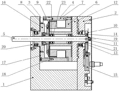
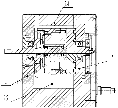
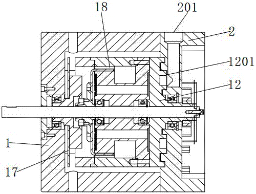
[0020] see Figure 1 to Figure 4 , the present invention provides a new type of dynamometer, including a front vertical plate 1, the rear side of the front vertical plate 1 is provided with a rear vertical plate 2 matching it; 101 is positioned and connected; an opening 3 is formed between the front vertical board 1 and the rear vertical board 2; a brake 4 is erected at the opening 3; the brake 4 is erected on the front vertical board 1 and the rear vertical board through the rotating shaft 5 Between the plates 2; the brake 4 includes a rotor 6 sleeved outside the rotating shaft 5, and the rotor 6 is covered with a stator 7 matched with it; the front end of the rotor 6 is fixed with a rotor end cover 8; the rotor end cover 8 A rotor cup 9 is connected, and the rotor cup 9 is sleeved outside the rotor 6; one end of the rotating shaft 5 runs...


PUM


Abstract

The invention discloses a novel dynamometer. The novel dynamometer comprises a front vertical plate, the rear side of which is provided with a rear vertical plate matched with the front vertical plate. The front vertical plate and the rear vertical plate are localized by positioning pins, and are connected together. An opening is formed between the front vertical plate and the rear vertical plate, and a brake is erected on the opening. The brake is erected between the front vertical plate and the rear vertical plate by a rotating shaft. The brake comprises a rotor disposed on the outer part of the rotating shaft in a sleeved way, and a stator matched with the rotor is disposed on the outer part of the rotor in a sleeved way. The front end of the rotor is fixedly provided with a rotor end cover. The rotor end cover is connected with a rotor cup, and the rotor cup is disposed on the outer part of the rotor. One end of the rotating shaft is extended out of the front vertical plate in a penetrating way, and the other end is disposed in the rear vertical plate. The end of the rotating shaft disposed in the rear vertical plate is connected with a code disc. The novel dynamometer is advantageous in that heat dissipation performance is better, and operation is more stable; during the operation of the dynamometer, hot air is led to the outside the first time, and a rapid cooling effect is achieved, and therefore the stable and normal operation of the dynamometer is guaranteed.

Description

technical field [0001] The invention relates to a new type of dynamometer. Background technique [0002] The dynamometer can be used to test the torque, speed, power, etc. of the engine, and can also be used as a loading device for the gearbox, reducer, and gearbox to test them. Traditional dynamometers use sensors to sense the torque of the engine, The speed, power, etc. are digitized, and the front and rear supports of the dynamometer are mostly split structures. The machining of the bearing holes on the front and rear support structures is prone to errors, resulting in errors in assembly accuracy and affecting measurement accuracy. [0003] During the operation of the dynamometer, high temperature will be generated inside the dynamometer. Most dynamometers will set cooling pipelines in the stator and use cooling water to cool down. However, this way of cooling has requirements on the structure and does not It is not suitable for all types of dynamometers, and the cooling...

Claims


Application Information

Patent Timeline
Patent Type & Authority Applications(China)
IPC IPC(8): G01L3/24
CPCG01L3/24Y02E10/72
Inventor 孙红辉王维锐李广平
Owner 台州市光中电器制造有限公司
Why Eureka
Try Eureka