Cooling device used in automobile part machining process

A technology for auto parts and processing, applied in applications, household components, home appliances, etc., can solve the problems of lower production efficiency and long cooling time of auto parts, and achieve the effect of improving production efficiency and rapid cooling

Inactive Publication Date: 2019-08-13
安徽佰尧电子科技有限公司
View PDF0 Cites 2 Cited by
  • Summary
  • Abstract
  • Description
  • Claims
  • Application Information

AI Technical Summary

Problems solved by technology

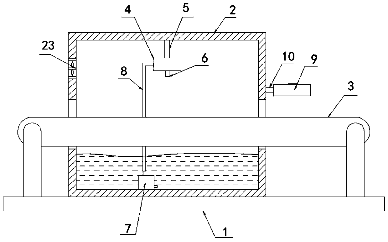
[0003] The purpose of the present invention is to solve the problem in the prior art that the cooling time of auto parts is longer after injection molding, which reduces the production efficiency of auto parts, and proposes a cooling device for the processing of auto parts

Method used


Image

  • Cooling device used in automobile part machining process
  • Cooling device used in automobile part machining process
  • Cooling device used in automobile part machining process

Examples


Embodiment Construction

[0023] The following will clearly and completely describe the technical solutions in the embodiments of the present invention with reference to the accompanying drawings in the embodiments of the present invention. Obviously, the described embodiments are only some, not all, embodiments of the present invention.

[0024] In describing the present invention, it should be understood that the terms "upper", "lower", "front", "rear", "left", "right", "top", "bottom", "inner", " The orientation or positional relationship indicated by "outside", etc. is based on the orientation or positional relationship shown in the drawings, and is only for the convenience of describing the present invention and simplifying the description, rather than indicating or implying that the referred device or element must have a specific orientation, so as to Specific orientation configurations and operations, therefore, are not to be construed as limitations on the invention.

[0025] refer to Figure ...


PUM


Abstract

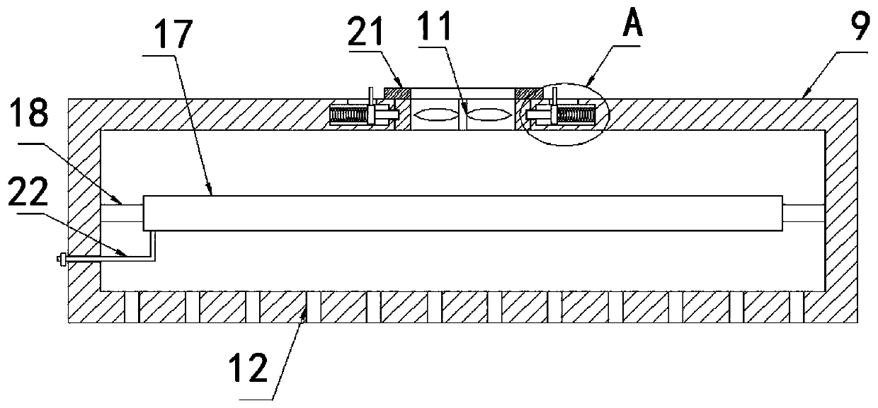
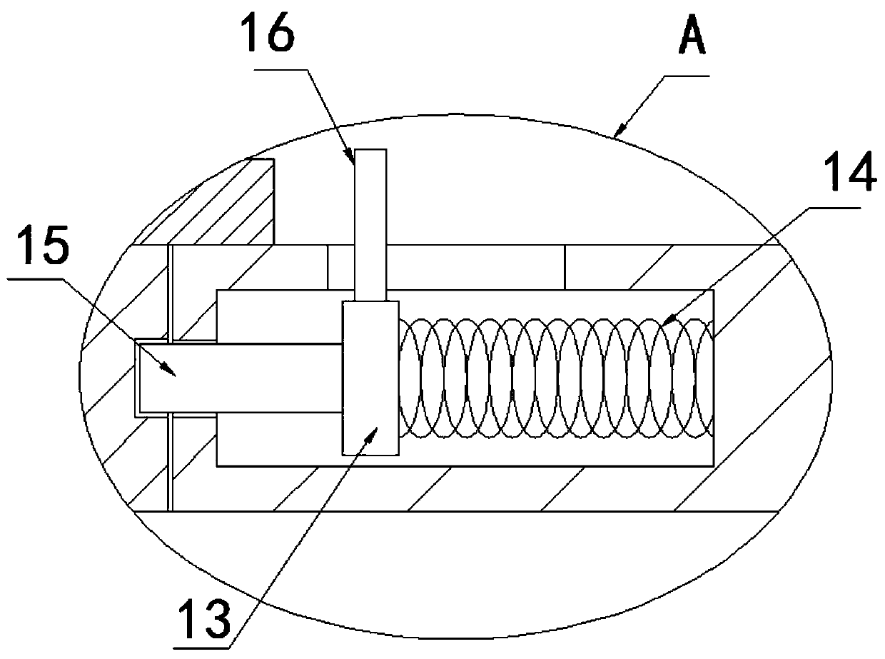
The invention relates to the technical field of cooling devices and discloses a cooling device used in the automobile part machining process. The cooling device comprises a base, a cooling tank and aconveying belt. The cooling tank is fixedly arranged on the upper surface of the base, and openings are formed in the left side and the right side of the cooling tank correspondingly. The conveying belt is fixedly arranged on the upper surface of the base and transversely penetrates the interior of the cooling tank. Cooling water is arranged at the bottom of an inner cavity of the cooling tank. Afirst hollow plate is longitudinally arranged on the top of the inner cavity of the cooling tank, and two first connecting rods are symmetrically and fixedly arranged on the upper surface of the firsthollow plate. The upper ends of the two first connecting rods are fixedly connected with the inner wall of the top of the cooling tank, and multiple water spraying pipes which are evenly distributedcommunicate with the lower surface of the first hollow plate in the length direction of the first hollow plate. By means of the cooling device, parts on the conveying belt can be rapidly cooled, the production efficiency of the parts is improved, and meanwhile water on the surfaces of the parts can be blown dry.

Description

technical field [0001] The invention relates to the technical field of cooling devices, in particular to a cooling device used in the processing of auto parts. Background technique [0002] There are many injection molded parts in the existing automobile parts. The injection molded parts are formed by the injection molding machine and then taken out of the mold. After demoulding, the temperature is relatively high, generally around 60°C, and it needs to be cooled before it can be processed. Production process, if it is placed in the air to cool naturally, it will take a long time and reduce the production efficiency of auto parts, and the high temperature for a long time will easily absorb impurities in the air during the cooling process, and at the same time cause the air in the production line to be turbid. For this reason, the present invention designs a kind of cooling device used in the machining process of auto parts. Contents of the invention [0003] The purpose o...

Claims


Application Information

Patent Timeline
Patent Type & Authority Applications(China)
IPC IPC(8): B29C45/72B29L31/30
CPCB29C45/7207B29L2031/30
Inventor 沈飞凤张亭亭石也伟
Owner 安徽佰尧电子科技有限公司
Why Eureka
Try Eureka