
Oppositely-opened radiative heating furnace and furnace body

A technology of radiant heating and radiant heating tubes, which is applied in the field of split radiant heating furnaces and furnace bodies, can solve the problems of low cost performance and poor rapid heating and cooling performance, and achieve the effects of low cost, low processing difficulty and broad application prospects

Active Publication Date: 2016-07-13
HARBIN INST OF TECH
View PDF11 Cites 3 Cited by
  • Summary
  • Abstract
  • Description
  • Claims
  • Application Information

AI Technical Summary

Problems solved by technology

[0004] The purpose of the present invention is to provide a split-type miniature radiation heating furnace and a furnace body to solve the problems of poor rapid heating and cooling performance and low cost performance in existing laboratory heating equipment

Method used


Image

  • Oppositely-opened radiative heating furnace and furnace body
  • Oppositely-opened radiative heating furnace and furnace body
  • Oppositely-opened radiative heating furnace and furnace body

Examples


specific Embodiment approach 1

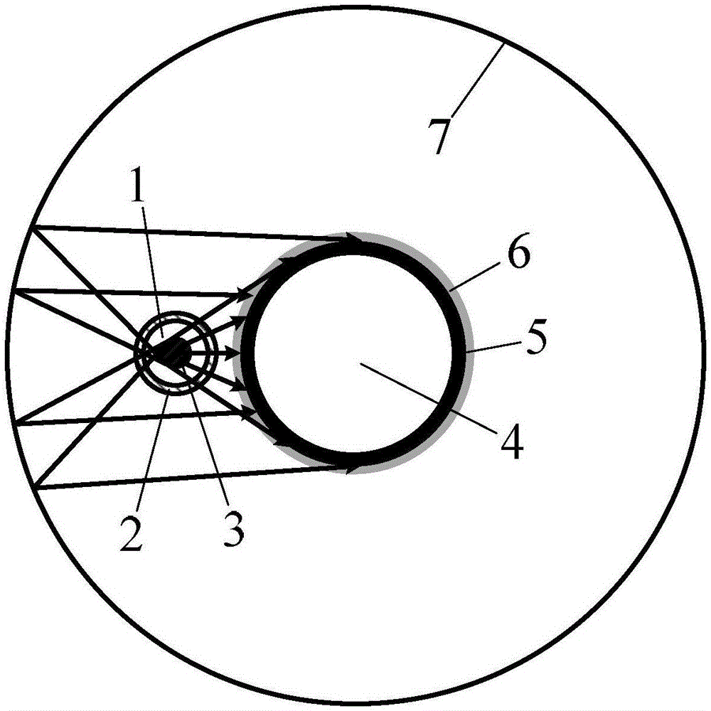
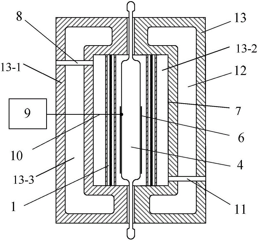
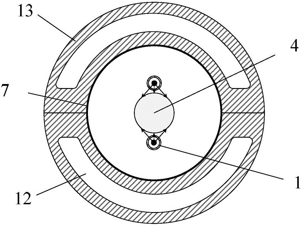
[0023] Specific implementation mode one: combine figure 1 and figure 2 The schematic diagram of the structure illustrates this embodiment. The furnace body of a split-type radiation heating furnace described in this embodiment is composed of two split 13-1, each split 13-1 has a concave cavity 13-2, and each split 13-1 There is a channel 13-3 for circulating cooling liquid to flow through on the wall body, when the two splits 13-1 are paired together, the two cavities 13-2 form a cylindrical furnace, and the wall 7 of the cylindrical furnace is smooth face.

specific Embodiment approach 2

[0024] Specific implementation mode two: combination figure 1 and figure 2 This embodiment is described. In this embodiment, the smooth surface (wall surface 7) is a metal polished surface with a surface roughness of less than 0.4 μm or a metal polished surface with a normal emissivity lower than 0.12. Various combined processing of milling, fine milling, grinding, electrochemical polishing and other processing methods can be realized. This method adopts a conventional and cheap method to obtain the mirror wall 7 that meets the requirements, avoids the strict requirements on the surface roughness of the mirror wall by the elliptical cylinder or parabolic cylinder based on directional reflection, and is easy to manufacture and use. The other components and connections of this embodiment are the same as those in the first embodiment.

specific Embodiment approach 3

[0025] Specific implementation mode three: combination figure 1 and figure 2To describe this embodiment, in this embodiment, more precisely, the wall surface 7 can be a metal polished surface with a surface roughness of less than 0.05 μm (or a normal emissivity of less than 0.05). That is, the smooth surface is a polished metal surface with a surface roughness less than 0.05 μm. The mirror wall 7 can be processed into a metal polished surface with a surface roughness of less than 0.05 μm or a normal emissivity of less than 0.05, through various processing methods such as rough turning, fine turning, rough milling, fine milling, grinding, and electrochemical polishing. A combination of processing to achieve. This way makes the insulation performance of the wall surface 7 better, makes the heating temperature higher than 1200° C., and can reduce the power consumption of heating. The other components and connections of this embodiment are the same as those of Embodiment 1 or ...


PUM

PropertyMeasurementUnit
surface roughnessaaaaaaaaaa
emissivityaaaaaaaaaa

Abstract

The invention provides an oppositely-opened radiative heating furnace and a furnace body, belongs to the field of heating devices used in laboratories and aims at solving the problems of poor rapid heating and cooling performance and low cost performance of existing heating devices used in the laboratories.The furnace body is composed of two sections, wherein each section is provided with a sunken cavity, a wall body of each section is provided with a channel for circulating cooling liquid to flow through, the two cavities form a cylindrical hearth when the two section are oppositely combined together, and the wall face of the cylindrical hearth is a smooth and clean face.The heating furnace comprises a heating element, the furnace body and a temperature controller, wherein the heating element is a radiative heating tube, the furnace body comprises the cylindrical hearth with the smooth and clean wall face, the radiative heating tube is close to the surface of a heated object, and the surface of the heated object is coated with a high-emissivity coating so as to strengthen radiative heating.The furnace body is provided with a gas purging channel to achieve rapid cooling of the hearth, and the circulating cooling liquid flows through the whole furnace wall to ensure cooling of a whole mirror wall.The oppositely-opened radiative heating furnace and the furnace body can be used for a heating tube type reactor.The furnace body is compact and high in performance cost ratio.

Description

technical field [0001] The invention relates to a split radiation heating furnace and a furnace body, belonging to the field of laboratory heating equipment, in particular to the field of heating equipment for tubular reactors. Background technique [0002] Conventional laboratory heating furnaces generally use refractory materials or low thermal conductivity materials as insulation layers; large heat capacity and low thermal conductivity lead to large thermal inertia, low heating and cooling rates (usually slower than 30°C / min), heating furnace maintenance and electric heating element replacement inconvenient. Patent applications with publication numbers CN86207267, CN101685052A, CN201222023, and CN104011491A disclose a class of electric heating furnaces that use elliptical or parabolic cylinders to directional reflect radiation to heat objects. The heating object can realize the rapid temperature rise of the object to be heated. It is usually used for heat treatment of sm...

Claims


Application Information

Patent Timeline
Patent Type & Authority Applications(China)
IPC IPC(8): F27B17/02F27D11/00F27D19/00
CPCF27B17/02F27D11/00F27D19/00F27D2019/0003F27D2019/0037
Inventor 孙绍增郭洋洲赵义军孟顺刘鹏唐文博
Owner HARBIN INST OF TECH
Learn More