
Color film substrate and display panel

A color filter substrate and display panel technology, which is applied in the fields of instruments, nonlinear optics, optics, etc., can solve the problem that the color filter substrate cannot meet the requirements at the same time.

Active Publication Date: 2017-09-22
BOE TECH GRP CO LTD +1
View PDF4 Cites 8 Cited by
  • Summary
  • Abstract
  • Description
  • Claims
  • Application Information

AI Technical Summary

Problems solved by technology

[0006] The present invention at least partly solves the problem that the existing color filter substrates cannot simultaneously meet the requirements of avoiding color crossover and improving transmittance, and provides a color filter substrate and a display panel that can simultaneously meet the requirements of avoiding color crossover and improving transmittance

Method used


Image

  • Color film substrate and display panel
  • Color film substrate and display panel
  • Color film substrate and display panel

Examples


Embodiment 1

[0033] like Figure 2 to Figure 8 As shown, this embodiment provides a color filter substrate.

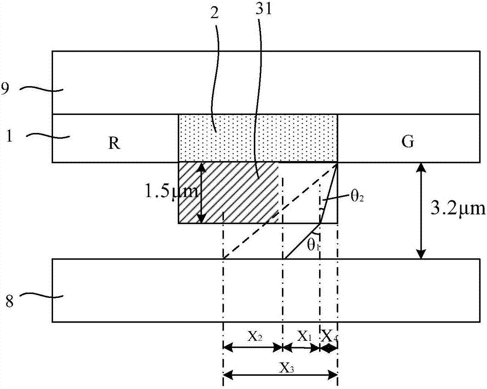
[0034] The color filter substrate is used to form a display panel (such as a liquid crystal display panel) by boxing with a box-matching substrate 8 (such as an array substrate), and an intermediate medium (such as liquid crystal) is filled in the display panel. On the side, that is, the display light is emitted from the display panel after passing through the color filter substrate.

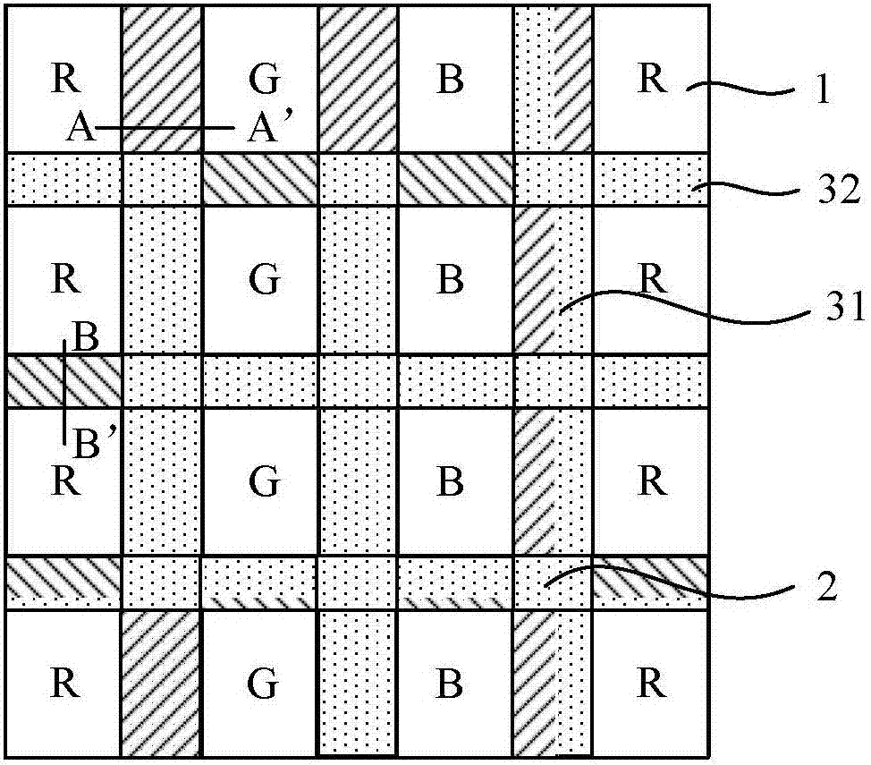
[0035] The color filter substrate of this embodiment includes a base 9 on which a plurality of spaced color filter films 1 are provided, and a black matrix 2 is provided between adjacent color filter films 1 .

[0036] like figure 2 As shown, a plurality of color filter films 1 are arranged on the base 9 of the color filter substrate, and each color filter film 1 corresponds to a pixel and has the same color as the pixel corresponding to it; There is a gap between them, and a black matrix 2 for b...

Embodiment 2

[0065] like Figure 2 to Figure 8 As shown, this embodiment provides a display panel, which includes:

[0066] The box matching substrate 8 and the color filter substrate that are boxed together, the color filter substrate is the above-mentioned color filter substrate and is located on the light emitting side of the display panel;

[0067] An intermediate medium is filled between the cell substrate 8 and the color filter substrate.

[0068] That is to say, the above color filter substrate can be combined with another substrate to form a display panel, and the display panel is filled with the above-mentioned intermediate medium, so that each transparent layer can function.

[0069] Of course, it should be understood that the color filter substrate should be located at the light emitting side of the display panel at this time.

[0070] Preferably, the display panel is a liquid crystal display panel; the cell-to-cell substrate 8 is an array substrate; and the intermediate mediu...


PUM

PropertyMeasurementUnit
Thicknessaaaaaaaaaa

Abstract

The invention provides a color film substrate and a display panel and belongs to the technical field of color film substrates. The problems that an existing color film substrate cannot meet the requirements of avoiding color crossing avoidance and increasing penetration rate simultaneously can be at least partially solved. The color film substrate comprises a base, wherein a plurality of interval color filtering films are arranged on the base, black matrixes are arranged between adjacent color filtering films, and a high refraction transparent layer is arranged on one side, away from the base, of each black matrix which is arranged between the color filtering films of different colors; the refraction index of the high refraction transparent layers is higher than that of the black matrixes, and intermediate mediums are mediums, wherein a display panel which is composed of the color film substrate and a box substrate is filled with the mediums.

Description

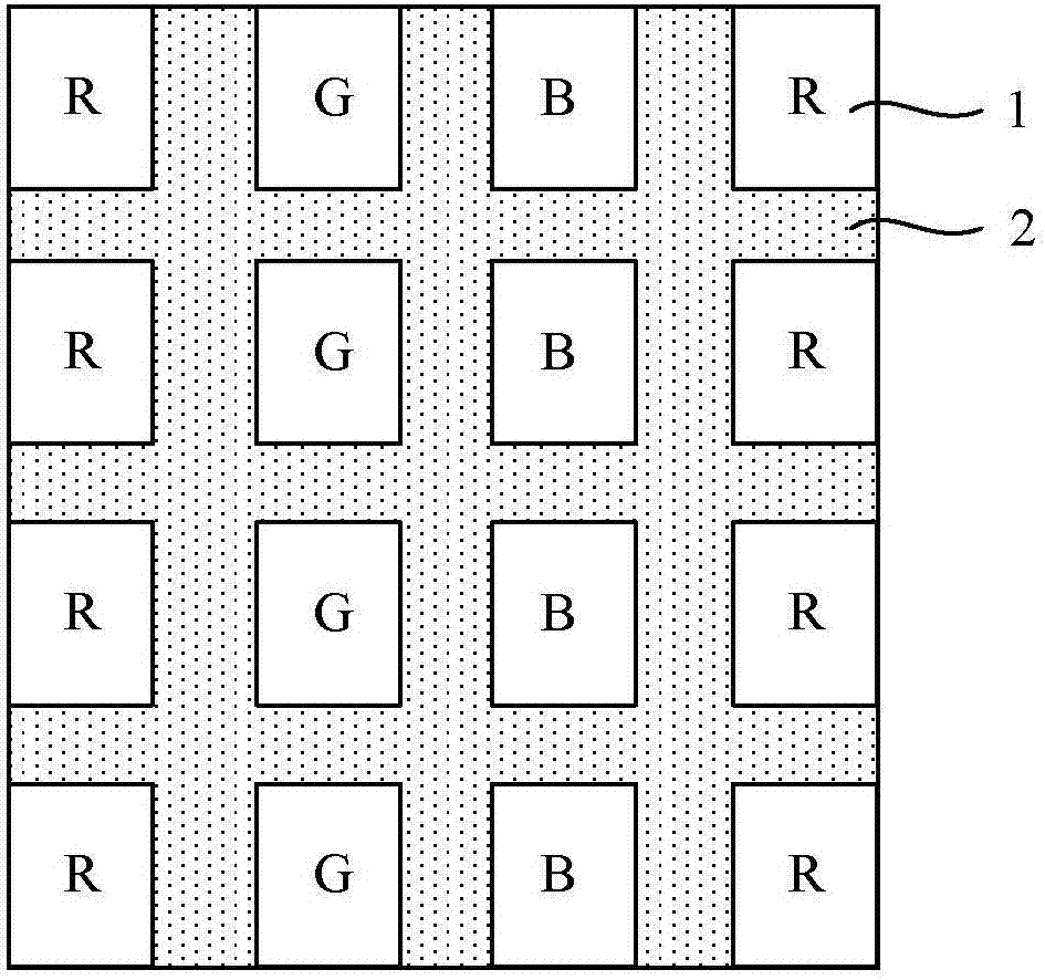
technical field [0001] The invention belongs to the technical field of color filter substrates, and in particular relates to a color filter substrate and a display panel. Background technique [0002] The liquid crystal display panel is composed of an array substrate and a color filter substrate boxed together, and liquid crystal is filled between the two substrates, and the color filter substrate is located on the light emitting side of the liquid crystal display panel (the side away from the backlight source). [0003] like figure 1 As shown, there are a plurality of color filter films 1 distributed at intervals on the base of the color filter substrate, each color filter film 1 has the same color as its corresponding pixel, and black color filter films 1 are arranged between adjacent color filter films 1. matrix2. Among them, the black matrix 2 is used to block the light emitted from the gap between adjacent color filter films 1, so the larger the width of the black mat...

Claims


Application Information

Patent Timeline
IPC IPC(8): G02F1/1335
CPCG02F1/133526G02F1/133512G02F1/133514
Inventor 张新亚张前前王春王坤刘玉琪
Owner BOE TECH GRP CO LTD
Learn More