Display screen, display device and mobile terminal

A display and display layer technology, applied in static indicators, instruments, electrical components, etc., can solve the problems of low fingerprint recognition efficiency of fingerprint modules, easy blocking of fingerprint module sensing signals, and reduced user experience

Active Publication Date: 2017-09-22
GUANGDONG OPPO MOBILE TELECOMM CORP LTD
View PDF10 Cites 62 Cited by
  • Summary
  • Abstract
  • Description
  • Claims
  • Application Information

AI Technical Summary

Problems solved by technology

In the display screen, the display layer is driven by the driving device to display images. However, the driving device is easy to block the sensi

Method used


Image

  • Display screen, display device and mobile terminal
  • Display screen, display device and mobile terminal
  • Display screen, display device and mobile terminal

Examples


no. 1 example

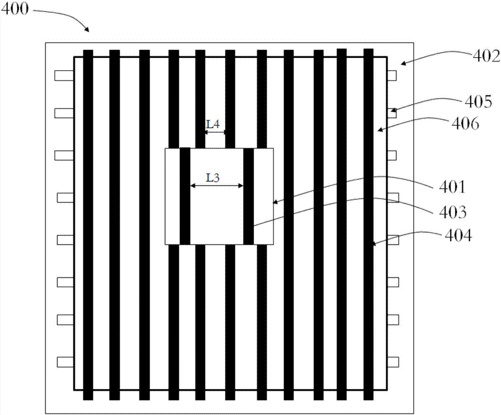
[0037] see Figure 4 , the arrangement of the first scan line 115 and the second scan line 116 is the same, and the first scan line 115 is connected to the second scan line 116 . That is, the first scan line 115 and the second scan line 116 are collinear. The arrangement of the first data line 117 and the second data line 118 is the same, and the first data line 117 is connected to the second data line 118 . That is, the first data line 117 and the second data line 118 are collinear. The arrangement pitch of the first thin film transistors 113 is greater than the arrangement pitch of the second thin film transistors 114 . Such a structural design reduces the shading area of ​​the fingerprint identification area 111 by increasing the arrangement spacing of the first thin film transistors 113, thereby increasing the light transmittance of the fingerprint identification area 111, thereby promoting more optical signals. Through the display screen 100, the optical signal receive...

no. 2 example

[0044] see Image 6 , the arrangement pitch of the first scan lines 115 is greater than the arrangement pitch of the second scan lines 116 . The arrangement of the first data lines 117 is the same as that of the second data lines 118 , and the first data lines 117 are connected to the second data lines 118 . That is, the first data line 117 and the second data line 118 are collinear. The arrangement pitch of the first thin film transistors 113 is greater than the arrangement pitch of the second thin film transistors 114 . Such a structural design, compared with the first embodiment, further reduces the shading area of ​​the fingerprint recognition area 111 by increasing the arrangement pitch of the first thin film transistors 113 and the arrangement pitch of the first scanning lines 115 , so as to further increase the light transmittance of the fingerprint identification area 111, and then promote more light signals to pass through the display screen 100, so as to increase t...

no. 3 example

[0046] see Figure 7 , the arrangement of the first scan lines 115 is the same as that of the second scan lines 116 , and the first scan lines 115 are connected to the second scan lines 116 . That is, the first scan line 115 and the second scan line 116 are collinear. The arrangement pitch of the first data lines 117 is greater than the arrangement pitch of the second data lines 118 . The arrangement pitch of the first thin film transistors 113 is greater than the arrangement pitch of the second thin film transistors 114 . Such a structural design, compared with the first embodiment, further reduces the shading area of ​​the fingerprint recognition area 111 by increasing the arrangement pitch of the first thin film transistors 113 and the arrangement pitch of the first data lines 117, Thereby further increasing the light transmittance of the fingerprint identification area 111, and then prompting more light signals to pass through the display screen 100, so as to increase th...


PUM


Abstract

The invention provides a display screen. The display screen comprises a display layer, wherein the display layer comprises a fingerprint recognition area and a peripheral area adjacent to the fingerprint recognition area; the fingerprint recognition area is provided with first driving devices; the peripheral area is provided with second driving devices; and the arrangement space of the first driving devices is greater than the arrangement space of the second driving devices. The invention provides a display device which comprises the display screen and an optical fingerprint module, wherein the optical fingerprint module is located at one side, deviating from the users, of the display screen; and the optical fingerprint module is arranged at a position corresponding to the fingerprint recognition area so as to conveniently transmit and receive optical signals through the fingerprint recognition area. The invention furthermore provides a mobile terminal. Through arranging the driving devices with large arrangement spaces in the fingerprint recognition area of the display area and arranging the optical fingerprint module under the fingerprint recognition area, the fingerprint recognition correctness of the optical fingerprint module is improved.

Description

technical field [0001] The invention relates to the technical field of electronic equipment, in particular to a display screen, a display device and a mobile terminal. Background technique [0002] In the prior art, the fingerprint identification module is arranged outside the display area of ​​the display screen to avoid obstructing the display. However, such a structural design makes the screen-to-body ratio (the ratio of the display area to the entire display screen) of the display area smaller, which affects user experience. In order to avoid damaging the existing display screen structure, technicians propose to arrange the fingerprint identification module under the display screen. In the display screen, the driving device is used to drive the display layer to display images. However, the driving device can easily block the sensing signal of the fingerprint module, resulting in low efficiency of fingerprint recognition by the fingerprint module and reducing user experi...

Claims


Application Information

Patent Timeline
IPC IPC(8): G06K9/00H01L27/12H01L27/32
CPCH01L27/1214G06V40/1318H10K59/65G09G3/3216G09G3/3225G09G2340/0407G09G2354/00H10K59/121H10K59/131H01L27/14678
Inventor 杨乐张海平
Owner GUANGDONG OPPO MOBILE TELECOMM CORP LTD
Why Eureka
Try Eureka