Receiver and assembly process thereof

An assembly process and technology for receivers, applied in the field of receivers, can solve the problems of inability to achieve modularization and complicated installation process.

Inactive Publication Date: 2017-09-22
SUZHOU YICHUAN TECH CO LTD
View PDF1 Cites 2 Cited by
  • Summary
  • Abstract
  • Description
  • Claims
  • Application Information

AI Technical Summary

Problems solved by technology

[0005] Therefore, the technical problem to be solved by the present invention is to overcome the problem that when the thickness of t

Method used


Image

  • Receiver and assembly process thereof
  • Receiver and assembly process thereof
  • Receiver and assembly process thereof

Examples


Embodiment 1

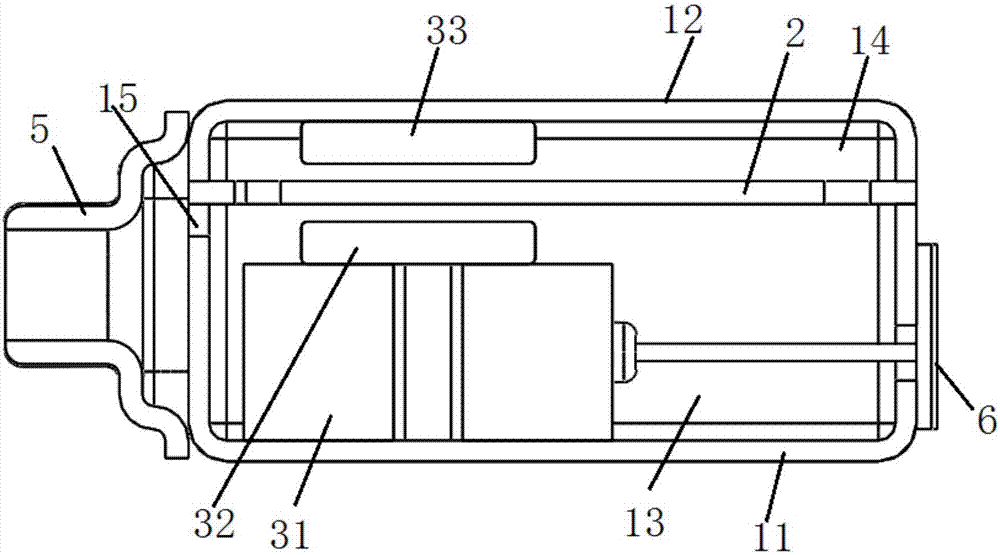
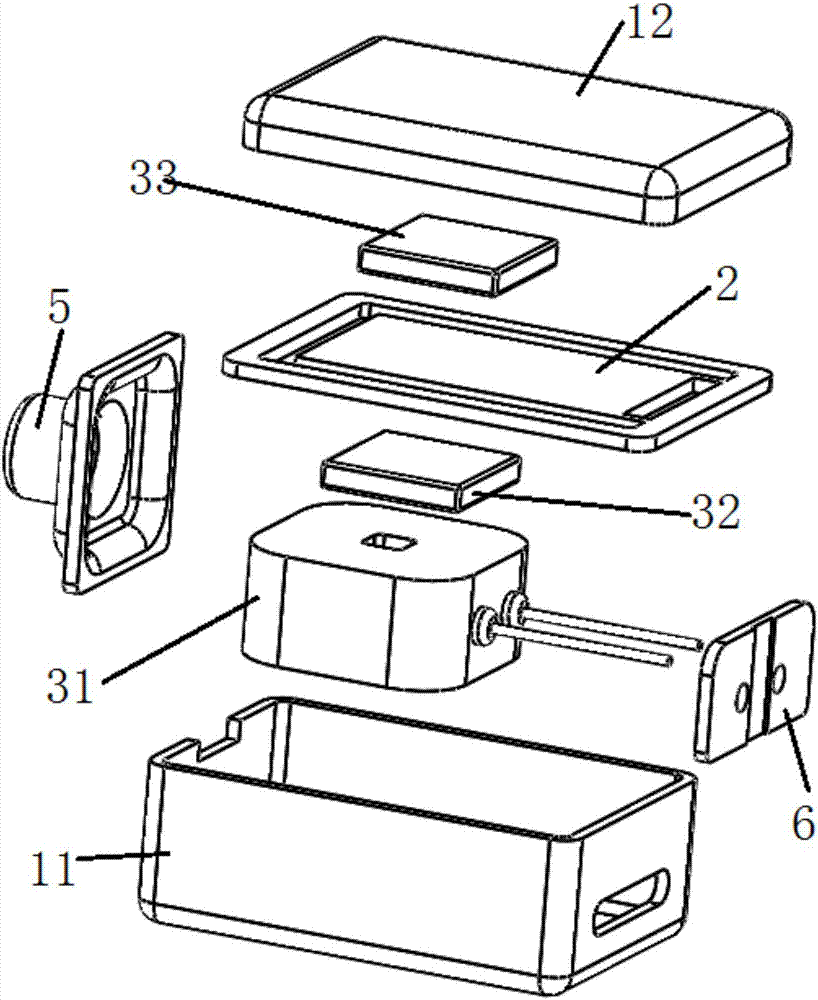
[0089] This embodiment provides a receiver, such as Figure 1 to Figure 3 As shown, it includes a housing 1 , a diaphragm mechanism 2 and an electromagnetic drive mechanism 3 .

[0090] like figure 2 and image 3 As shown, the shell 1 has a first shell 11 made of a first bottom surface and a side wall, and a second shell 12 made of a second bottom surface and a side wall; the second shell 12 is detachably connected to the first shell 11 buckle and encircle the inner cavity. The diaphragm mechanism 2 is arranged in the inner cavity, and the inner cavity of the housing 1 is divided into an installation cavity 13 close to the first bottom surface and a sound emitting cavity 14 close to the second bottom surface; Figure 14 and Figure 15As shown, the diaphragm mechanism 2 includes a fixed frame 22 , a reed 21 and a sound diaphragm 23 . The fixed frame 22 has a hollow inner cavity, and one end of the reed 21 is connected to the fixed frame 22 through the fixed end 211 for th...

Embodiment 2

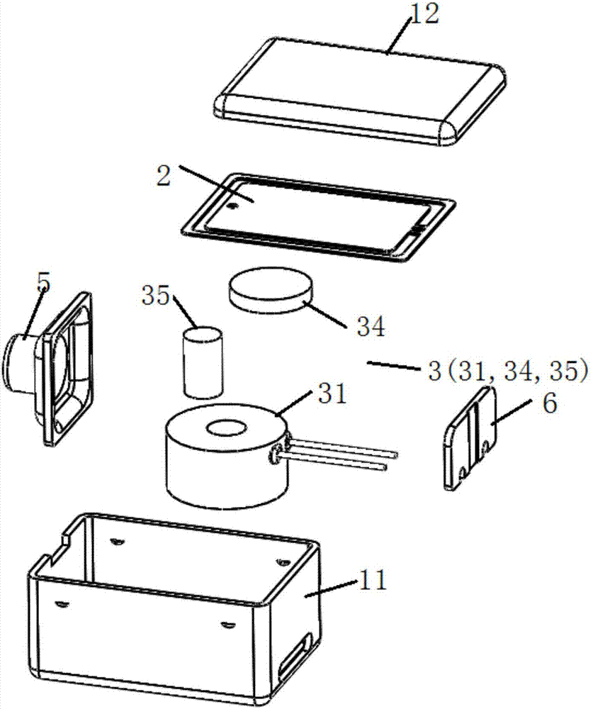
[0136]This embodiment provides a receiver, such as Figure 7 and Figure 8 As shown, compared with the receiver provided in Embodiment 1, the only difference is that the reed 21 is made of non-magnetic material, and the electromagnetic drive mechanism 3 is different from the electromagnetic drive mechanism 3 provided in Embodiment 1. The electromagnetic drive Mechanism 3 includes a coil 31 and a third magnet 34 is fixed on the side surface of the reed 21 facing away from the sound membrane 23; the coil 31 and the third magnet 34 are located in the same cavity, and the coil 31 and the third magnet 34 A gap is reserved between the ends facing each other, and a vibration space for the reed is formed between the top of the coil 31 and the second bottom surface of the second housing 12 .

[0137] The electromagnetic driving mechanism 3 of this structure is in the process of driving the reed 21 to reciprocate and vibrate: if the polarity of the third magnet 34 towards the end of th...

Embodiment 3

[0162] This embodiment provides a receiver, such as Figure 12 and Figure 13 As shown, compared with the receiver provided in Embodiment 2, the only difference is that one end of the third magnet 34 is fixed on the reed 21, and the other end extends vertically into the inner cavity of the coil 31 and is connected to the coil The inner wall surfaces of the magnets 31 are separated from each other, and a distance is reserved between the bottom of the third magnet 34 and the first bottom surface of the first housing 11 . The iron core is fixed in the inner cavity of the coil 31 , but there is a gap between the top of the iron core and the bottom of the third magnet 34 .


PUM

PropertyMeasurementUnit
Caliberaaaaaaaaaa

Abstract

The invention discloses a receiver and its assembly process. The receiver includes a shell, a diaphragm mechanism and an electromagnetic drive mechanism. The diaphragm mechanism is arranged in the shell, which divides the inner cavity of the shell into an installation cavity and a sound cavity; the diaphragm mechanism has a fixed frame, a reed and a sound film, and the sound film is pre-fixed on the fixed frame independently of the shell; the electromagnetic The drive mechanism is used to generate an electromagnetic field to drive the reciprocating vibration of the suspended end of the reed in the diaphragm mechanism. The assembly process is as follows: fix the first coil on the inner wall of the first casing perpendicular to the diaphragm mechanism; install the diaphragm mechanism on the inner wall of the first casing or the second casing, or the first casing and the second casing On the opposite mouth edge of the casing, a distance is reserved between the first coil and the diaphragm mechanism. Since the sound membrane is pre-fixed on the fixing frame independently of the housing, the diaphragm mechanism as a whole is a separate module. When installing the receiver, the diaphragm mechanism only needs to be fixed on the housing through the fixing frame, thus simplifying the installation process of the receiver.

Description

technical field [0001] The invention relates to the technical field of receivers, in particular to a receiver and an assembly process thereof. Background technique [0002] The receiver is an electroacoustic device that converts audio electrical signals into audio signals without sound leakage. It is widely used in communication terminal equipment such as mobile phones, fixed phones, and earphones to realize audio output. [0003] With the continuous development of mobile devices, the structure of the receiver is constantly updated. For example, the receiver disclosed in Chinese patent document CN103067806A integrates the reed and flapping mechanism in the traditional moving iron receiver to form a new diaphragm mechanism. Including the shell, the diaphragm mechanism installed horizontally in the inner cavity of the shell; the diaphragm mechanism includes an E-shaped reed, a coil set on the root of the E-shaped middle wall, and the other end of the reed is used as the vibrat...

Claims


Application Information

Patent Timeline
IPC IPC(8): H04R9/08H04R9/02
CPCH04R9/08H04R9/02H04R2410/00
Inventor 吴哲
Owner SUZHOU YICHUAN TECH CO LTD
Why Eureka
Try Eureka