Mask strip connection method and device as well as mask plate

A bonding method and bonding device technology, which are applied in ion implantation plating, metal material coating process, coating, etc., can solve the problems of low alignment accuracy and long time consumption, and achieve the goal of improving production efficiency and reducing alignment time. Effect

Active Publication Date: 2017-09-26
BOE TECH GRP CO LTD +1
View PDF7 Cites 5 Cited by
  • Summary
  • Abstract
  • Description
  • Claims
  • Application Information

AI Technical Summary

Problems solved by technology

[0006] Aiming at the problems of long time-consuming alignment process and low alignment accuracy of the existing whole mask plate welded by mask strips, the present invention provides a mask strip joining method, a joint device, and a mask plate

Method used


Image

  • Mask strip connection method and device as well as mask plate
  • Mask strip connection method and device as well as mask plate
  • Mask strip connection method and device as well as mask plate

Examples


Embodiment 1

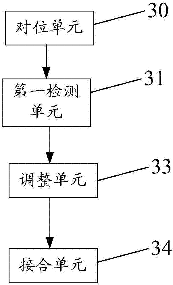
[0035] This embodiment provides a bonding device for mask strips, such as figure 2 As shown, it includes an alignment unit 30, a first detection unit 31, an adjustment unit 33 and a joint unit 34; wherein, the alignment unit 30 is used to align the frame of the mask strip at this stage; the first detection unit 31 is connected with the The alignment unit is connected to detect the position deviation of the frame after the alignment to obtain the first compensation data; the adjustment unit 33 is connected to the first detection unit and is used to adjust the position of the mask strip of this stage according to the first compensation data. Pixel coordinate reference; the bonding unit 34 is used to fix the mask strip of the current stage to the frame.

[0036] In the mask strip bonding device of this embodiment, the first detection unit 31 connected to the alignment unit 30 acquires the positional deviation of the frame after alignment as the first compensation data, and the a...

Embodiment 2

[0042] This embodiment provides a method for bonding mask strips, such as Figure 4 shown, including the following steps:

[0043] S1. Align the frame of the mask strip at the current level, and detect the position deviation of the frame after alignment to obtain the first compensation data;

[0044] S2. Adjust the pixel coordinate reference of the mask strip at the current level according to the first compensation data;

[0045] S3. Fix the mask strip of the current stage to the frame according to the pixel coordinate reference.

[0046] In the bonding method of the mask bar in this embodiment, the position deviation of the frame after alignment is used as the first compensation data to compensate to the pixel coordinate reference, so the difference between the actual position of the mask bar frame and the target position can be set ± a μm For a larger range, this can make the mask strip frame of this level fall into the threshold range of alignment accuracy in a short peri...

Embodiment 3

[0048] This embodiment provides a method for bonding mask strips, which is combined by using the bonding device for mask strips in Embodiment 1, such as Figure 5 As shown, it specifically includes the following steps:

[0049]S01a, the alignment unit 30 aligns the frame of the mask strip at the current stage, and the first detection unit 31 detects the position deviation of the frame after alignment to obtain first compensation data.

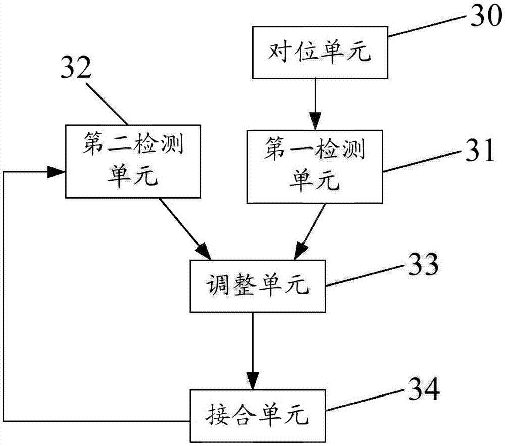
[0050] S01b, the second detection unit 32 obtains the second compensation data of the mask bar frame of the current stage according to the average value of the pixel position deviation of the fixed mask bar.

[0051] S02. The adjustment unit 33 adjusts the pixel coordinate reference of the mask strip at the current stage according to the first compensation data and the second compensation data.

[0052] S03. The joining unit 34 fixes the mask strip of the current stage to the frame according to the pixel coordinate reference.

[0053] That is...


PUM


Abstract

The invention provides a mask strip connection method and device as well as a mask plate, belongs to the technical field of display, and aims to solve the problems that the overall mask plate formed by welding mask strips is long in alignment process time consumption and low in alignment precision. According to the mask strip connection method and device as well as the mask plate, the positional deviation of a frame after alignment is taken as first compensation data to compensate for the pixel coordinate basis, so that the difference between the actual position of the mask strip frame and the target position is set within a wider range, the mask strip frame at the level can fall into the threshold range of the alignment precision within a shorter time, the alignment time is greatly reduced, the alignment process is prevented from entering the dead circulation, and the production efficiency is improved while the fixed connection precision of the mask strips of the mask plate is not affected.

Description

technical field [0001] The invention belongs to the field of display technology, and in particular relates to a method for bonding mask strips, a bonding device, and a mask plate. Background technique [0002] The fine metal mask (FMM Mask) mode is to vapor-deposit the red, green, blue and other organic materials of the Organic Light Emitting Diode (OLED) onto the Low Temperature Poly-silicon (LTPS) according to a predetermined procedure. ) on the backplane, use the graphics on the FMM to vapor-deposit organic materials such as red, green, and blue to the specified positions. [0003] When producing OLED display panels in assembly line, such as figure 1 As shown, generally, the display panel motherboard 1 with a complete layer structure is formed first, and then the display panel motherboard 1 is cut to obtain each sub-display panel 2 . During the manufacturing process of the display panel motherboard 1 , multiple sub-display panel 2 products are usually formed by a synchr...

Claims


Application Information

Patent Timeline
Patent Type & Authority Applications(China)
IPC IPC(8): C23C14/04C23C14/24C23C14/12
CPCC23C14/042C23C14/12C23C14/24
Inventor 林治明李宝军王震黄俊杰唐富强
Owner BOE TECH GRP CO LTD
Why Eureka
Try Eureka