Method for transverse stiffness control over high-pier large-span concrete continuous girder bridge and bridge
A technology of lateral stiffness and control method, applied in bridges, buildings, etc., can solve problems such as affecting the safety of bridges, driving safety and stability and comfort, and unable to control the lateral stiffness of continuous girder bridges.
- Summary
- Abstract
- Description
- Claims
- Application Information
AI Technical Summary
Problems solved by technology
Method used
Image
Examples
Embodiment 1
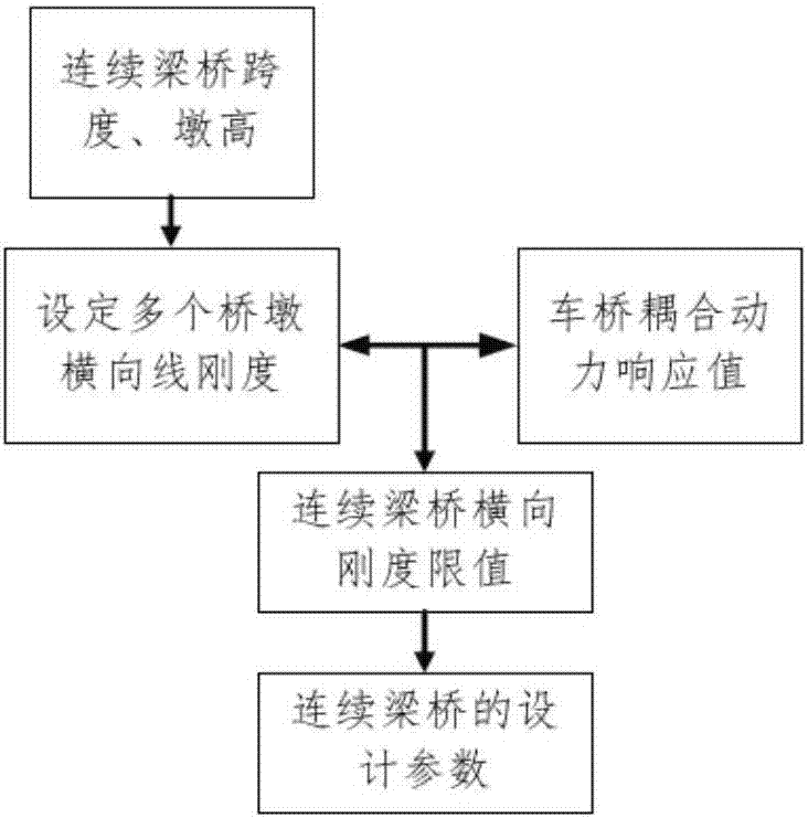
[0075] Such as figure 1 As shown, the lateral stiffness control method of long-span concrete continuous girder bridge with high piers includes the following steps:
[0076] a. Determine the span of the continuous girder bridge and the pier height of the bridge;
[0077] b. Under the setting of different bridge pier transverse line stiffnesses, the corresponding vehicle-bridge coupling dynamic response values are obtained;
[0078] c. Compare and draw the curve of the transverse line stiffness of the pier and the corresponding vehicle-bridge coupling dynamic response value;
[0079] d. Take the vehicle-bridge coupling dynamic response values obtained in step c to meet the corresponding specified limit values, thereby obtaining the transverse stiffness limit value of the continuous girder bridge. The specified limit values of the vehicle-bridge coupling dynamic response values include those that meet the safety of the bridge structure Bridge evaluation indicators, and ...
Embodiment 2
[0114] In this embodiment, the transverse stiffness control method of the high-pier and long-span concrete continuous girder bridge in Example 1 is adopted, and the transverse stiffness is controlled for the continuous girder bridge with a span of (60+100+60) m and a pier height of 100 m .
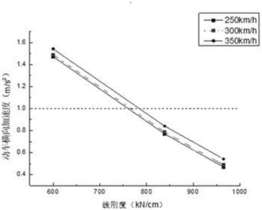
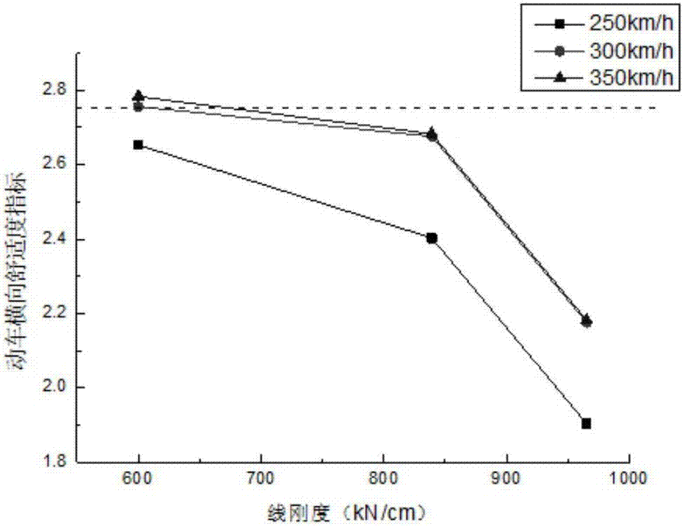
[0115] In order to analyze the lateral stiffness limit of continuous girder bridges, according to the vehicle-bridge coupled vibration theory, using the bridge structure dynamic analysis program BDAP, the typical high piers in mountainous areas with a pier height of 100 m and a main span of 100 were established by using the spatial finite element method. The dynamic analysis model of the whole bridge. The vehicle model adopts the German ICE3 high-speed train. By adjusting the foundation stiffness of the model, different working conditions of the transverse line stiffness of the pier top are obtained, and then the influence of the transverse stiffness of different bridge piers on the dynamic...
Embodiment 3
[0121] In this embodiment, the transverse stiffness control method of the high-pier and long-span concrete continuous girder bridge in Embodiment 1 is adopted, and the continuous girders with a span of (48+80+48) m and pier heights of 60 m, 80 m and 100 m respectively The transverse stiffness of the bridge is controlled, and the limit of the transverse stiffness of the high-pier and long-span concrete continuous girder bridge of this span is obtained.
[0122] In order to obtain the limit value of the lateral stiffness of the continuous girder bridge, according to the vehicle-bridge coupled vibration theory, the bridge structure dynamic analysis program BDAP is used, and the space finite element method is used to establish a span of (48+80+48)m, and pier heights of 60m, 80m and 100m typical mountainous high-pier bridge full bridge dynamic analysis model, the vehicle model uses the German ICE3 high-speed train, by adjusting the foundation stiffness of the model to obtain differe...
PUM
 Abstract
Description
Claims
Application Information
 - R&D
- Intellectual Property
- Life Sciences
- Materials
- Tech Scout
- Unparalleled Data Quality
- Higher Quality Content
- 60% Fewer Hallucinations
Browse by: Latest US Patents, China's latest patents, Technical Efficacy Thesaurus, Application Domain, Technology Topic, Popular Technical Reports.
© 2025 PatSnap. All rights reserved.Legal|Privacy policy|Modern Slavery Act Transparency Statement|Sitemap|About US| Contact US: help@patsnap.com


