Eureka AIR delivers breakthrough ideas for toughest innovation challenges, trusted by R&D personnel around the world.

Pipeline switch valve

A technology of switching valves and pipelines, which is applied in the field of faucets, can solve the problems of inability to change direction completely, not easy to lift, and wet the body, and achieve the effect of compact and exquisite structure design, simple and reliable operation, and small space occupation

Inactive Publication Date: 2017-09-26
KAIPING YIZHAN VALVE CORE
View PDF9 Cites 1 Cited by
  • Summary
  • Abstract
  • Description
  • Claims
  • Application Information

AI Technical Summary

Problems solved by technology

The pull-type water distributor realizes the switching of the water outlet by lifting and pressing the handle. Its reversing function is affected by the water pressure.
The switchable water distributor uses a specific angle to switch the spool to switch the water outlet mode. When using it, it is easy to be unclear which outlet corresponds to the water outlet, and the user will be wet by the water flow if he is not paying attention.
In addition, the two types of water separators can only discharge water from one water outlet at a time, and cannot realize water discharge from two or three water outlets at the same time, and need to be constantly adjusted and switched during use, which is not conducive to a better shower experience

Method used


Image

  • Pipeline switch valve
  • Pipeline switch valve

Examples


Embodiment Construction

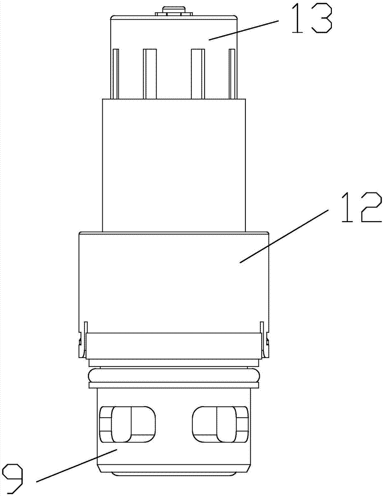
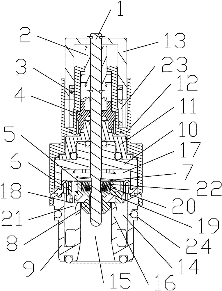
[0024] refer to figure 1 and figure 2 The pipeline switch valve provided by the present invention includes a shaft 1, a push rod 2, a compression spring 3, a sliding claw sleeve 4, a water sealing ring 5, a leather cup 6, a pressure spring 7, a leather cup seat 8, a water connection 9, The water separator 10, the receiving part 11, the valve sleeve 12, the cap 13, the slag discharge needle 21 and the fixing part 22.

[0025] The lower end of the valve sleeve 12 is connected to the water joint 9 by a buckle. The side wall of the water joint 9 is provided with a plurality of evenly arranged water inlet holes. The water joint 9 is provided with a water inlet chamber 14, a water outlet channel 15, and a partition The water retaining plate 16 of the water inlet chamber 14 and the water passage 15, the outer wall of the water connection 9 is provided with an annular groove 24 for accommodating a rubber sealing ring, and the water connection 9 is provided with a rubber sealing ring...


PUM


Abstract

The invention discloses a pipeline switch valve which comprises a valve sleeve, a water closing mechanism and a switch mechanism. The lower end of the valve sleeve communicates with a water swivel. A water insulator is arranged in the valve sleeve, and a pressure cavity is formed by the water insulator and the water closing mechanism. The water closing mechanism comprises a leather cup. A leather cup seat is arranged on the leather cup. A pressure relief hole is formed in the middle of the leather cup seat. A water sealing ring is arranged on the pressure relief hole. The switch mechanism comprises a shaft rod. A cover cap is arranged at the upper end of the shaft rod. A compressed spring is arranged between the cover cap and the valve sleeve so that the shaft rod can have a pressed state and a bounced state. The shaft rod penetrates through the pressure relief hole and is provided with a pressure relief groove. In the bounced state, the shaft rod is in close contact with a sealing ring, in the pressed state, the pressure relief groove of the shaft rod right faces the sealing ring, and liquid in the pressure cavity is drained through the pressure relief hole. The pipeline switch valve can be installed in waterways of a combined shower faucet, the function that each water outlet is controlled independently is achieved, a user can control the water outlet mode clearly and conveniently, and the shower experience that water is discharged out of a plurality of water outlets at the same time can be met.

Description

technical field [0001] The invention relates to the field of faucets, in particular to a pipeline switch valve. Background technique [0002] In the combined shower faucet, there are usually two or three water outlets. If there are three water outlet functions: hand shower, overhead shower and spout, a water divider is required to switch the water outlets. At present, there are two common types of water separators on the market, namely pull-type water separators and switchable water separators. The pull-type water distributor realizes the switching of the water outlet by lifting and pressing the handle. Its reversing function is affected by the water pressure. It is difficult to lift when the water pressure is too high, and the water flow cannot be completely reversed when the water pressure is too low. The switchable water distributor uses a specific angle to switch the valve core to switch the water outlet mode. When using it, it is easy to not know which outlet correspon...

Claims


Application Information

Patent Timeline
IPC IPC(8): F16K7/16F16K31/44
CPCF16K7/16F16K31/44
Inventor 施仙兵沈君法
Owner KAIPING YIZHAN VALVE CORE
Why Eureka
Eureka Blog
Learn More