
Ammunition-parachute separation rotating device of parachute used for ammunition

A technology of a rotating device and a parachute, which is applied to projectiles, offensive equipment, weapon types, etc., can solve the problems of restricting the application of parachutes for ammunition, adjusting the attitude of ammunition that cannot be delivered, and reducing the accuracy of ammunition delivery. performance, low cost and simple structure

Active Publication Date: 2017-09-26
XIANGYANG HONGWEI AIRCRAFT
View PDF4 Cites 4 Cited by
  • Summary
  • Abstract
  • Description
  • Claims
  • Application Information

AI Technical Summary

Problems solved by technology

However, due to the twisting of the parachute during the delivery of the ammunition, the existing parachute for ammunition affects the normal opening of the parachute in the air or the abnormal operation of the parachute after the parachute is opened, so it cannot effectively complete the delivery of the ammunition. The attitude adjustment work reduces the accuracy of ammunition delivery; on the other hand, after the existing ammunition parachute completes the attitude adjustment process, there is a risk that the ammunition and the parachute cannot be separated quickly and accurately. Failure to achieve rapid and accurate separation from the parachute will adversely affect the normal work of the ammunition to be delivered
The above-mentioned defects of existing ammunition parachutes have greatly affected the normal delivery of ammunition and limited the application of ammunition parachutes

Method used


Image

  • Ammunition-parachute separation rotating device of parachute used for ammunition
  • Ammunition-parachute separation rotating device of parachute used for ammunition

Examples


Embodiment Construction

[0023] In order to make the object, technical solution and advantages of the present invention clearer, the present invention will be further described in detail below in conjunction with the accompanying drawings and embodiments. It should be understood that the specific embodiments described here are only used to explain the present invention, not to limit the present invention.

[0024] In addition, the technical features involved in the various embodiments of the present invention described below can be combined with each other as long as they do not constitute a conflict with each other.

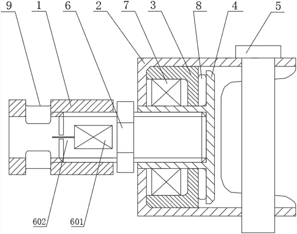
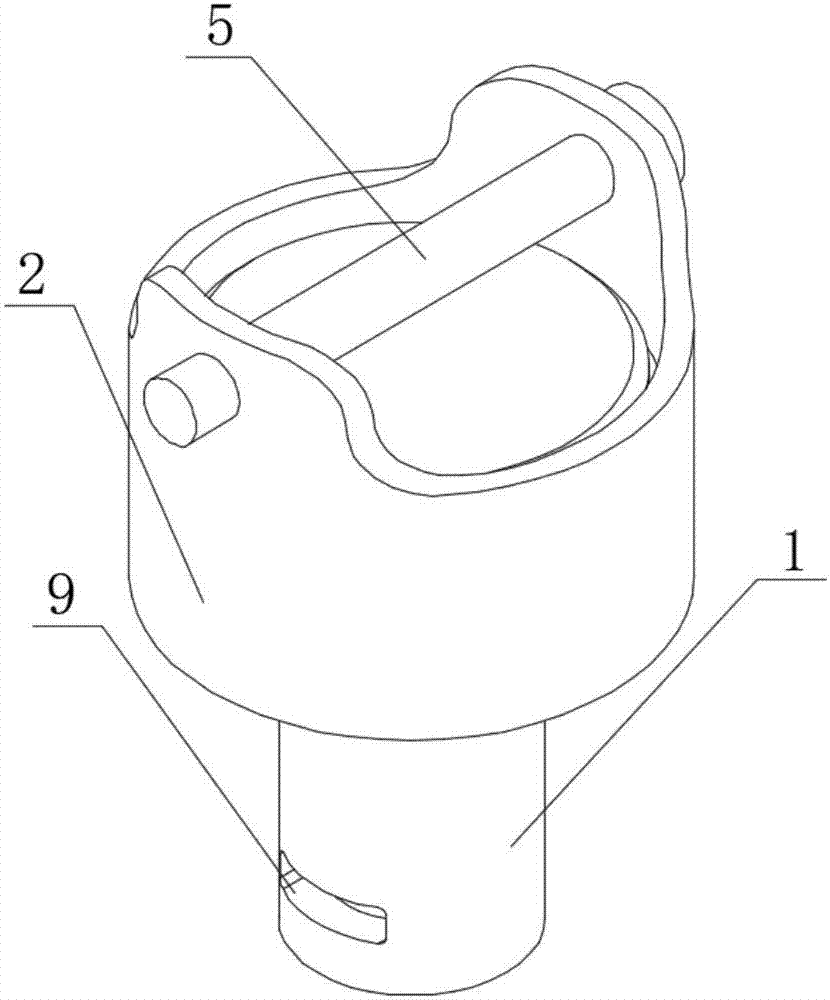
[0025] as attached Figure 1~2 Shown is a rotating device in a preferred embodiment in which, figure 1 It is an assembly diagram of the overall structure of the rotating device used for the separation of the ammunition parachute and parachute according to the embodiment of the present invention; figure 2 It is a schematic diagram of the overall structure of the rotating device used f...


PUM


Abstract

The invention discloses an ammunition-parachute separation rotating device of a parachute used for ammunition. The ammunition-parachute separation rotating device comprises an upper connector connected with ropes of the parachute, a lower connector connected with the ammunition, and an explosive bolt for enabling the upper connector to be connected with the lower connector. A connection shaft is arranged in the upper connector, quick and relative rotation of the upper connector and the connection shaft can be achieved by arranging a first rolling bearing in the upper connector, the upper connector and the lower connector are quickly and accurately separated through the explosive bolt after the ammunition is put in place, and accordingly, the effect that the ammunition is separated from the parachute is achieved. According to the ammunition-parachute separation rotating device, through the arrangement, the defect that the ropes of the parachutes are twisted in the ammunition delivery process can be effectively overcome, and the speed and accuracy of attitude adjusting of the ammunition are improved; and by means of the explosive bolt, on one hand, the upper connector and the lower connector can be firmly connected in the beginning, on the other hand, the ammunition can be rapidly and accurately separated from the parachute after reaching the specified height, and the ammunition delivery accuracy is effectively improved.

Description

technical field [0001] The invention belongs to the technical field of parachute application, and in particular relates to a rotating device used for ammunition parachute separation. Background technique [0002] Parachute is a kind of expandable aerodynamic reducer that utilizes the principle of air resistance and relies on inflation relative to air movement. With the continuous development of parachute technology, the application field of parachute has become wider and wider, and has been widely used in airborne airdrop, air deceleration, emergency rescue and aircraft recovery and other fields. [0003] Along with the application of parachute in the ammunition delivery field more and more widely, more and more ammunition uses the parachute to participate in the process of ammunition delivery. Some ammunition parachutes can realize the deceleration and attitude adjustment of the ammunition during the ammunition delivery process, so as to improve the accuracy of ammunition ...

Claims


Application Information

Patent Timeline
IPC IPC(8): F42B10/58
CPCF42B10/58
Inventor 郭炳磊徐志修李小鹏张正宇
Owner XIANGYANG HONGWEI AIRCRAFT
Learn More