Test rack system

A technology for testing racks and racks, applied in the field of testing, can solve the problems of easy to increase the probability of server failure, manual handling of servers, and many times of plugging and unplugging, so as to reduce the probability of bad appearance, and reduce the cost of erection and space. , reduce the effect of test equipment

Inactive Publication Date: 2017-09-26
INVENTEC PUDONG TECH CORPOARTION +1
View PDF5 Cites 0 Cited by
  • Summary
  • Abstract
  • Description
  • Claims
  • Application Information

AI Technical Summary

Problems solved by technology

[0011] In view of the above-mentioned shortcomings of the prior art, the purpose of the present invention is to provide a test rack system, which is used to solve the manual handling of servers

Method used


Image

  • Test rack system
  • Test rack system
  • Test rack system

Examples


Example Embodiment

[0040] The following describes the implementation of the present invention through specific specific examples. Those skilled in the art can easily understand other advantages and effects of the present invention from the content disclosed in this specification. The present invention can also be implemented or applied through other different specific embodiments, and various details in this specification can also be modified or changed based on different viewpoints and applications without departing from the spirit of the present invention. It should be noted that the following embodiments and the features in the embodiments can be combined with each other if there is no conflict.

[0041] It should be noted that the illustrations provided in the following embodiments only illustrate the basic idea of ​​the present invention in a schematic manner. The figures only show the components related to the present invention instead of the number, shape, and number of components in actual i...


PUM


Abstract

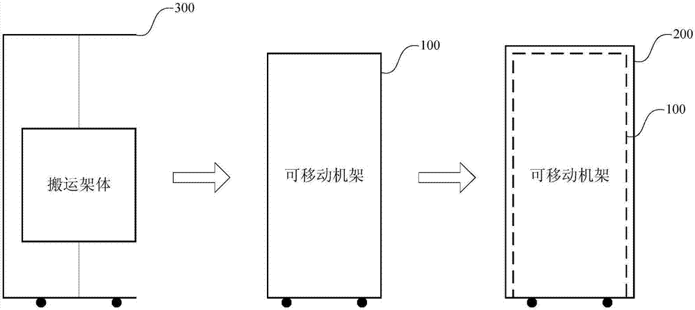
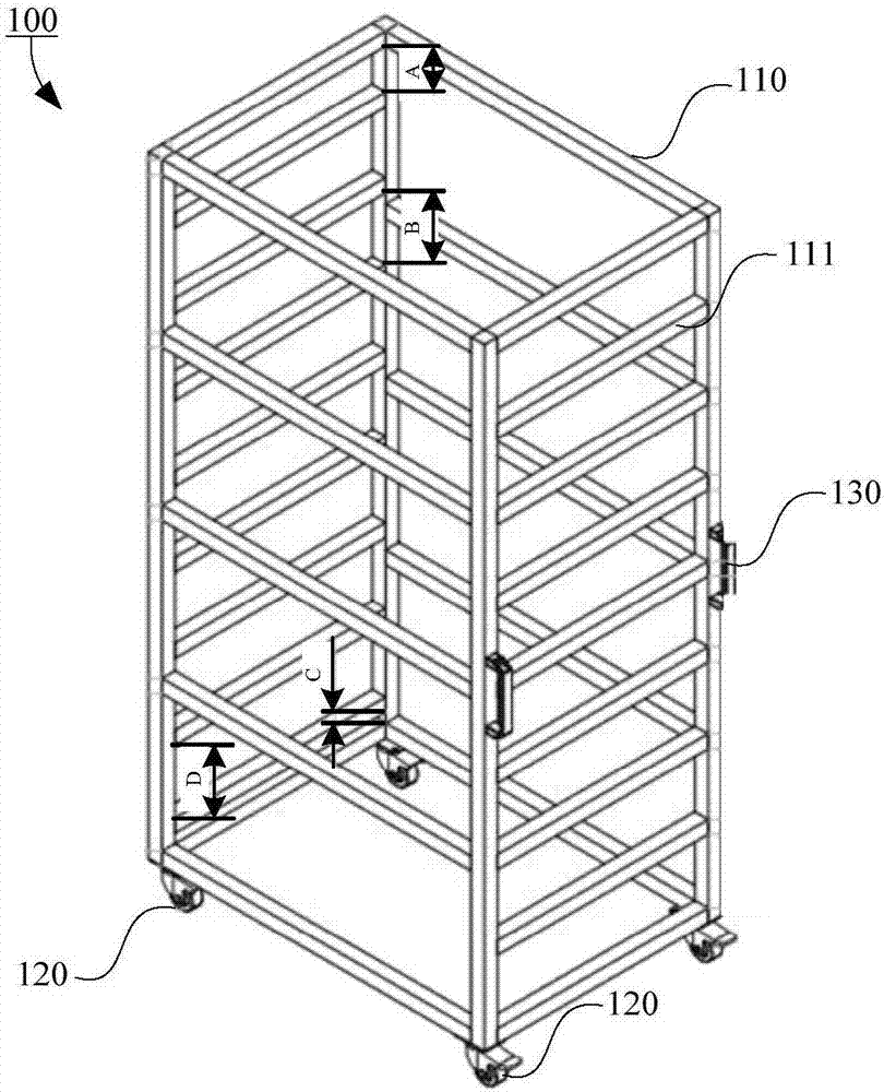
The invention provides a test rack system and applies to testing of at least one to-be-tested device. The test rack system comprises a movable rack and an outer frame, wherein the movable rack comprises a rack frame body and a first moving part; the first moving part supports motion of the rack frame body; a first detachable isolation layer is arranged in the rack frame body; the rack frame body and the first detachably isolation layer are combined to form at least one accommodating space for accommodating the to-be-tested device; the outer frame comprises an outer frame body which forms at least one storage space; all the storage spaces are used for storing the movable rack. Separate design is adopted for the outer frame and the movable rack, and the to-be-tested device can be fixed by the outer frame and is prevented from being carried continuously; the to-be-tested device can be carried conveniently and smoothly by means of the movable rack. Besides, a loading and unloading device is further designed and can be used for loading the to-be-tested device to the movable rack and unloading the to-be-tested device from the movable rack conveniently, and working pressure of a carrying worker is reduced.

Description

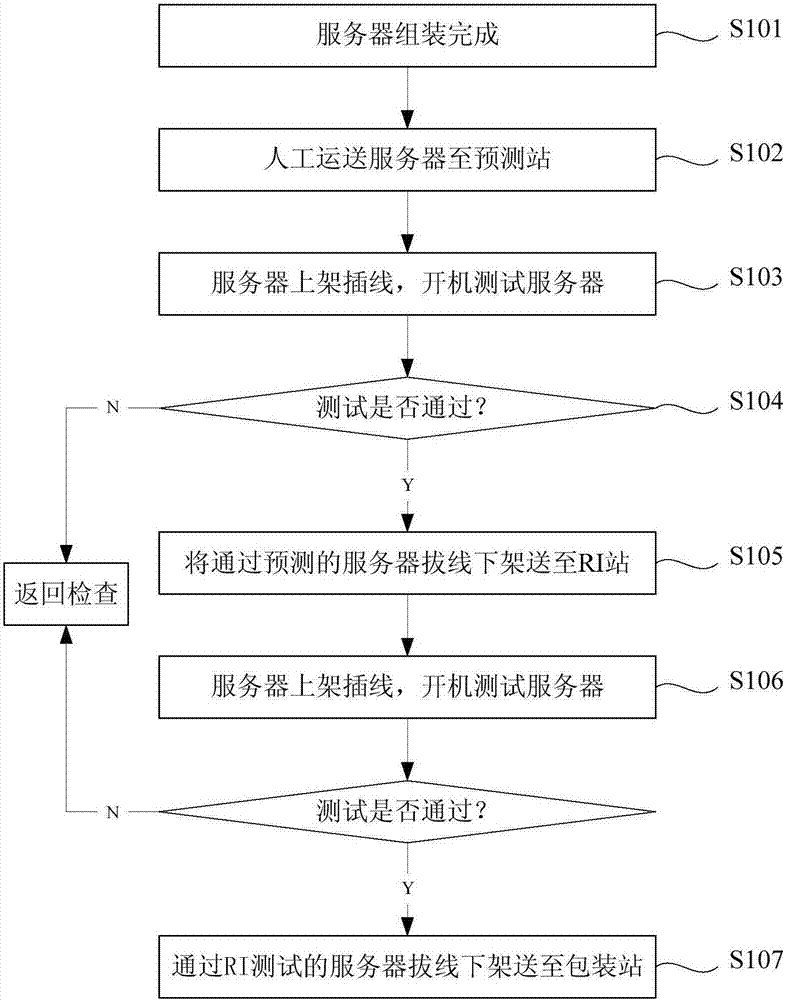
technical field [0001] The invention belongs to the technical field of testing, and relates to testing equipment, in particular to a testing rack system. Background technique [0002] In the existing server production line, the server needs to be transported twice from the assembly station to the prediction station, and then to the RI station, two times of putting on the rack and plugging in cables, and one time of unplugging and taking off the rack. For details, see figure 1 shown, including: [0003] S101, the server assembly is completed; [0004] S102, manually transporting the server to a prediction (pretest) station; [0005] S103, the server is put on the rack and plugged in, and the server is turned on for testing; [0006] S104, if the prediction is passed, execute the next step, otherwise return to check; [0007] S105, sending the predicted server unplugging to the RI (Running In) station; [0008] S106, the server is put on the rack and plugged in, and the s...

Claims


Application Information

Patent Timeline
IPC IPC(8): G01R31/01
CPCG01R31/013
Inventor 萧宗渊
Owner INVENTEC PUDONG TECH CORPOARTION
Why Eureka
Try Eureka