
Pressure gage

A technology of pressure gauge and liquid pressure, which is applied in the direction of fluid pressure measurement by changing the ohmic resistance, which can solve the problems of complex structure of pressure gauge, high cost, unfavorable maintenance, etc., to reduce test equipment and manpower and material resources, reduce impact, and debug and easy maintenance effect

Inactive Publication Date: 2014-06-04
上海朝辉压力仪器有限公司
View PDF10 Cites 0 Cited by
  • Summary
  • Abstract
  • Description
  • Claims
  • Application Information

AI Technical Summary

Problems solved by technology

[0004] The technical problem to be solved by the present invention is to provide a pressure gauge that simplifies the pressure gauge by adopting a built-in power supply and a low-power design method in order to overcome the defects of complex structure, high cost and unfavorable maintenance of the pressure gauge using a wired circuit in the prior art. The structure of the pressure gauge is improved, and the cost of maintenance and commissioning is effectively reduced

Method used


Image

  • Pressure gage

Examples


Embodiment Construction

[0027] The present invention will be further explained by way of examples below, but the present invention is not limited to the scope of the described examples.

[0028] The pressure gauge of this embodiment uses a low-power MCU, battery power supply, and periodic measurement methods, so that the power supply is built in the pressure gauge. On the one hand, the structure of the pressure gauge is reduced and the interference resistance is improved.

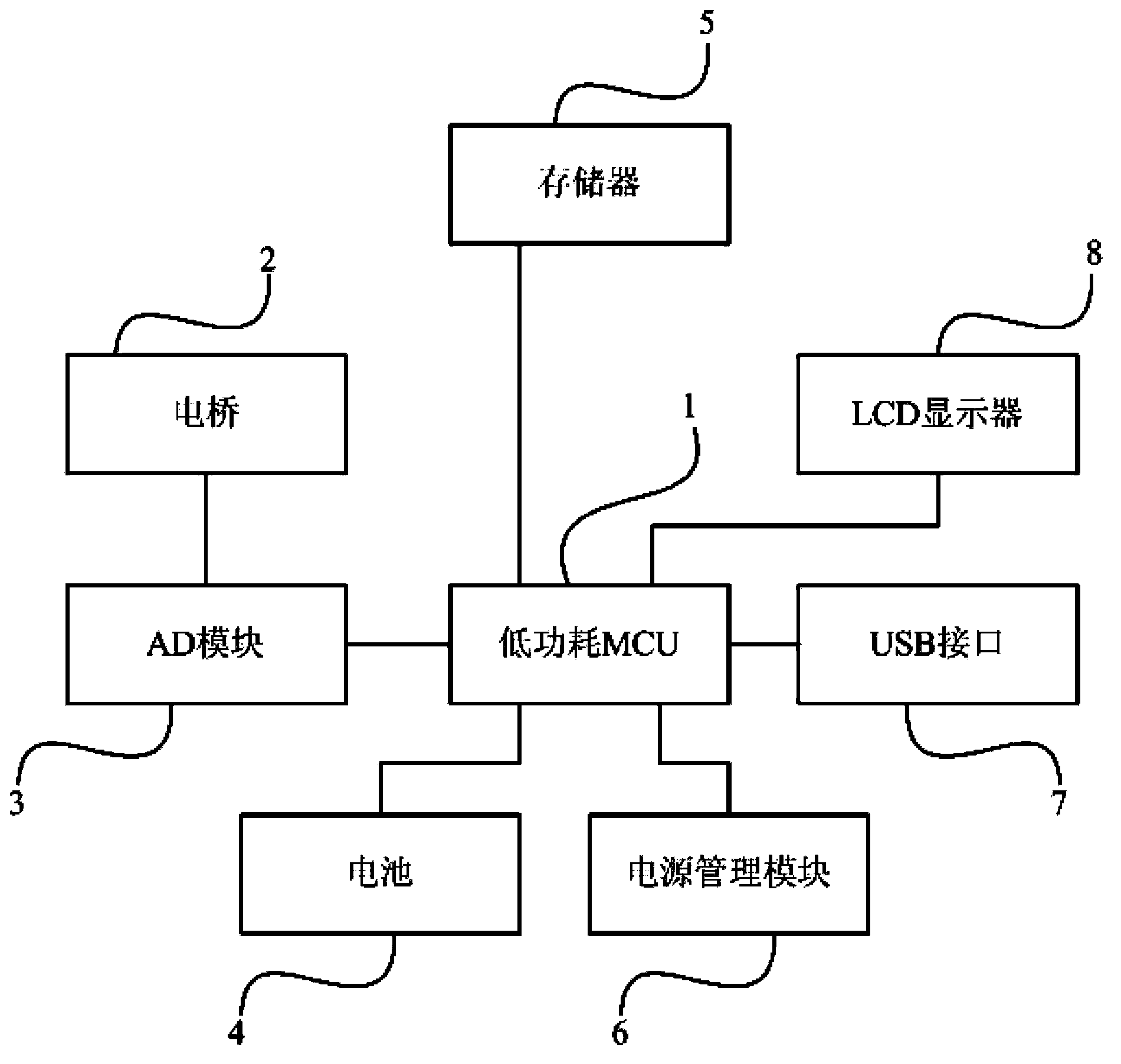
[0029] Specifically, such as figure 1 As shown, the pressure gauge of this embodiment includes a low-power MCU1, a bridge 2, an AD module 3, a battery 4, a memory 5, a power management module 6, a USB interface 7 and an LCD display 8.

[0030] The electric bridge 2 is composed of 4 strain gauges and attached to an elastic body (not shown in the figure), and the output of the electric bridge 2 composed of the strain gauges is connected to the AD module 3. The AD module 3 is connected to the low power consumption MCU1 through an SPI (High...


PUM


Abstract

The invention discloses a pressure gage for detecting the liquid pressure. The pressure gage comprises a processor, a bridge, an AD module, a battery and a display unit. The bridge is composed of at least four sensors. The AD module is used to convert a differential analog signal generated by the bridge into a digital signal. The processor is used to convert the digital signal into a display signal. The display unit is used to display the display signal. The processor is used to convert the digital signal into the display signal according to a time interval. The battery is used to supply power to the processor, the bridge, the AD module and the display unit. The pressure gage of the invention adopts the built-in power source mode, so the influences of an external power source on the circuit stability can be reduced, so that advantages of good anti-interference capacity and wide application field can be realized.

Description

Technical field [0001] The invention relates to a pressure gauge, in particular to a pressure gauge for measuring liquid pressure. Background technique [0002] In industrial engineering, enterprises used to manufacture chemical fibers, rubber, plastics, urban water supply pressure and urban sewage treatment, etc., need to monitor the production process of their products during the production process to control the production of products within the expected parameter range. This requires measuring production equipment for data collection and observation of production process variables including pressure, temperature and flow, etc., and records and saves these data for data analysis and processing. [0003] However, the power supply necessary for the operation of sensors and instruments in the field has caused the measurement system to be too complicated, which is a technical problem to be solved by all sensors at present. The traditional pressure gauge adopts the mechanical struct...

Claims


Application Information

Patent Timeline
Patent Type & Authority Applications(China)
IPC IPC(8): G01L9/04
Inventor 李凤奎伍正辉龙霞
Owner 上海朝辉压力仪器有限公司
Learn More