Drive unit for a wiper system

A drive unit and wiper technology, which is applied in the direction of electrical components, electric components, vehicle cleaning, etc., can solve the problems of high cost and high cost of drive units, and achieve improved durability and robustness, reliable force transmission, and accurate speed Adjustment effect

Active Publication Date: 2017-09-26
ROBERT BOSCH GMBH
View PDF8 Cites 0 Cited by
  • Summary
  • Abstract
  • Description
  • Claims
  • Application Information

AI Technical Summary

Problems solved by technology

[0005] A disadvantage of this prior art is that corresponding drive units are relatively complex and costly and are theref...

Method used


Image

  • Drive unit for a wiper system

Examples


Embodiment Construction

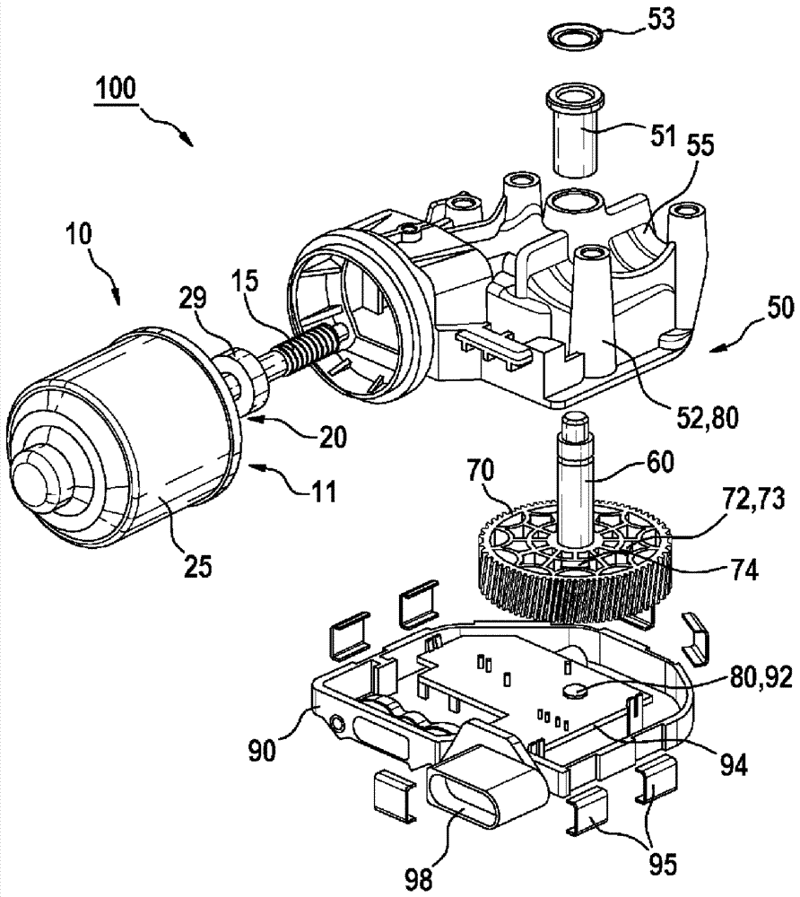
[0040] figure 1 An exemplary embodiment of a drive unit 100 according to the invention for a wiper system is shown. The drive unit 100 preferably has an electronically commutated drive motor 10 which, in the exemplary embodiment shown and for the purposes of the invention, is preferably embodied as a brushless DC motor 11 . The drive motor 10 schematically has a rotor 20 which is connected in a rotationally fixed manner to the drive shaft 15 and which drives the drive shaft 15 . Furthermore, the drive motor 10 has a housing 25 and at least one bearing 29 , wherein the drive shaft 15 of the drive motor 10 or the rotor 20 is mounted in the housing 25 in a rotationally movable manner, preferably via the bearing 29 . Furthermore, the drive unit 100 has a transmission 50 with an output shaft 60 drivable by the drive shaft 15 . The drive shaft 15 of the drive motor 10 and the output shaft 60 of the transmission 50 are preferably arranged at a predetermined angle to one another, pr...


PUM


Abstract

The invention relates to a drive unit (100) for a wiper system, comprising an electronically commutated drive motor (10) having a drive shaft (15), and a transmission (50) having an output shaft (60) that can be driven by the drive shaft (15). According to the invention, at least one angular position sensor (80) for determining a respective angular position of the output shaft (60) is assigned to the output shaft (60) of the transmission (50).

Description

technical field [0001] The invention relates to a drive unit for a windshield wiper system, which has an electronically commutated drive motor and a transmission, the drive motor has a drive shaft, and the transmission has a drive shaft drivable by the drive shaft. driven shaft. Furthermore, the invention relates to a method for ascertaining the angular position of a drive shaft of an electronically commutated drive motor of such a drive unit. Background technique [0002] Such drive units for wiper systems are known from the prior art. For example, DE 10 2009 047 566 A1 describes a drive unit for a windshield wiper, in which the drive shaft is driven by an electric motor and is connected to the output element via a worm gear, wherein the electric motor is pivotably mounted, This enables the distance between the axis of the driven element and the drive shaft to be adjusted. [0003] A drive unit for a wiper system is known from DE 10 2009 055 396 A1, in which the drive mo...

Claims


Application Information

Patent Timeline
IPC IPC(8): B60S1/16H02K29/08H02K29/10H02K7/116
CPCB60S1/166H02K7/1166H02K29/08H02K29/10H02K11/215
Inventor P.布劳恩M.福施特
Owner ROBERT BOSCH GMBH
Why Eureka
Try Eureka