Vibration compensator apparatus

A vibration compensation and equipment technology, applied in mechanical equipment, inertia force compensation, vibration suppression adjustment, etc., can solve problems such as system efficiency reduction, achieve simple and precise control, and reduce size.

Inactive Publication Date: 2012-10-31
WAERTSILAE SCHWEIZ AG
View PDF6 Cites 4 Cited by
  • Summary
  • Abstract
  • Description
  • Claims
  • Application Information

AI Technical Summary

Problems solved by technology

However, in cases where vibration compensation is not required, vibration compensation equipment leads to a reduction in the efficiency of the overall system

Method used


Image

  • Vibration compensator apparatus
  • Vibration compensator apparatus
  • Vibration compensator apparatus

Examples


Embodiment Construction

[0042] An embodiment of the vibration compensation device according to the present invention will be explained below. The vibration compensation device according to this embodiment can be implemented so as to cancel vibrations originating from an internal combustion engine installed on the hull of a ship.

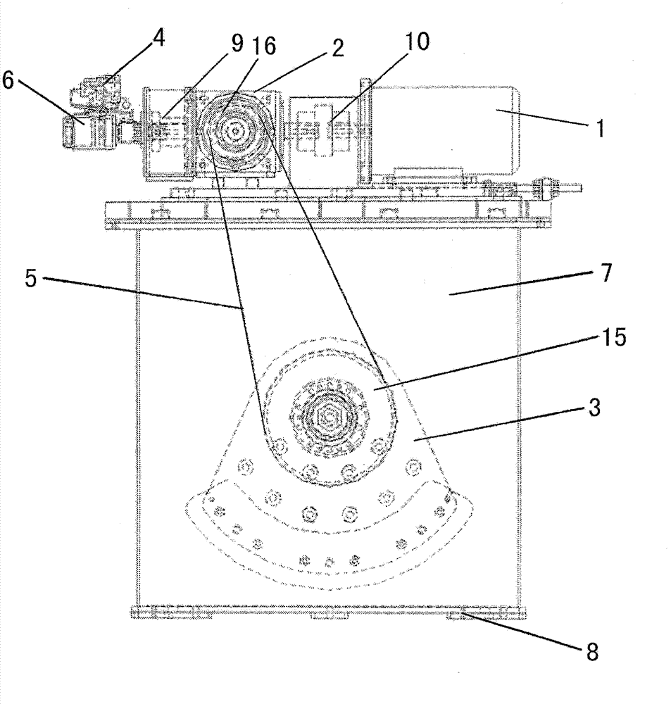
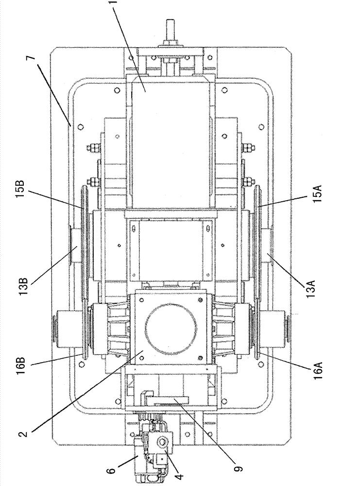
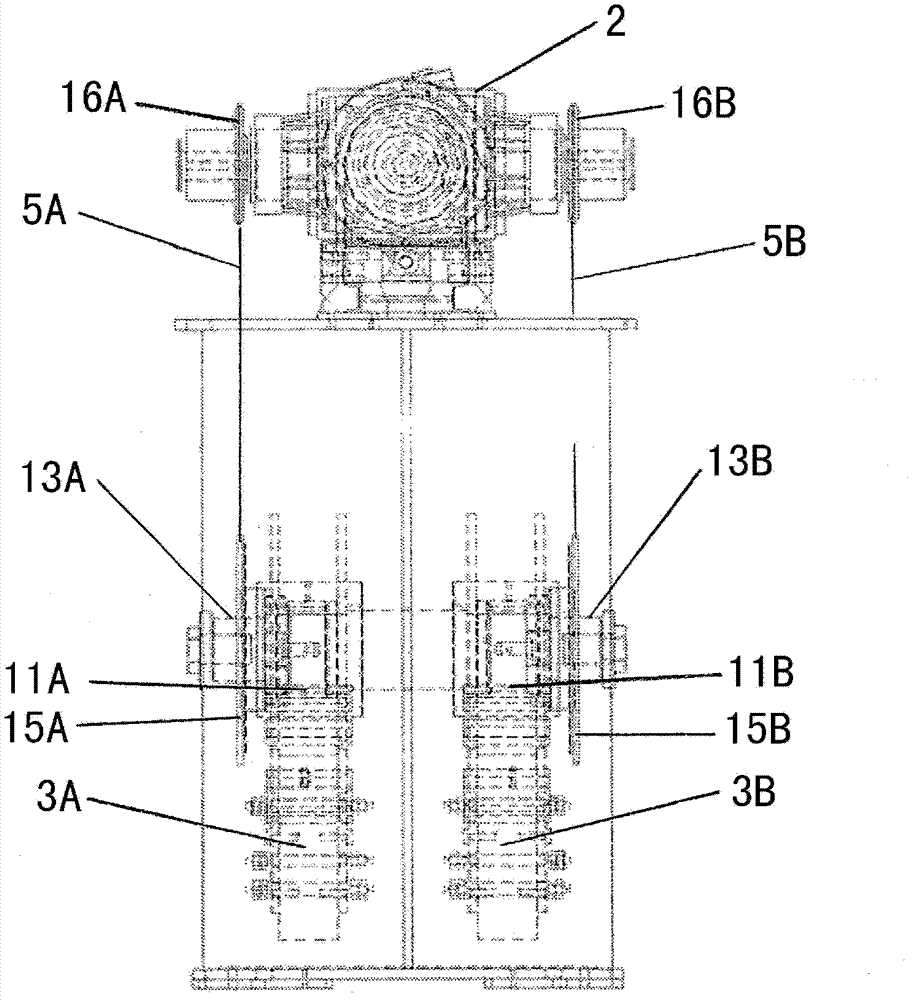
[0043] First, the overall configuration of the vibration compensation device is explained based on the drawings. Such as figure 1 As shown, the vibration compensation device includes a housing 7 with a support 8 disposed at the bottom of the housing 7. The support 8 is formed so that the housing 7 can be mounted to the structure requiring vibration compensation via the support 8. The housing 7 with the support 8 is mounted to the aforementioned structure so that the inertial force generated during the operation of the equipment can be between the equipment and the structure (for example, the hull of a ship with an internal combustion engine as a driving source) transfer.

[0...


PUM


Abstract

A vibration compensator apparatus includes two rotor elements (3A, 3B) which are rotatable in opposite rotational directions. The vibration compensator apparatus is driven by a main power source (1) for rotating the rotor elements (3A, 3B) in a continuous operation, wherein an additional starting power source (6) is provided which is employed for starting the rotation of the rotor elements (3A, 3B) from the stopped condition.

Description

Technical field [0001] The present invention relates to a vibration compensation device suitable for compensating for vibrations generated by inertial forces derived from the operation of the internal combustion engine to which the device is allocated. Background technique [0002] Vibration compensation equipment is known, which is used to offset vibrations generated by the operation of an internal combustion engine, such as an engine mounted on a ship's hull. Specifically, the vibration compensation device according to the related art includes two rotor elements rotating in opposite rotation directions. These rotor elements are eccentric with respect to the rotation axis and rotate at the same rotation speed in order to provide inertial force in the estimated direction. The known device is installed in a structure that forms a vibration system with an internal combustion engine. The rotation speed and rotation phase of the rotating rotor element are controlled based on the ro...

Claims


Application Information

Patent Timeline
IPC IPC(8): F16F15/22
CPCB63H21/302F16F15/223F16F15/22F02N5/00
Inventor S・K・楠达C・范吉塞尔
Owner WAERTSILAE SCHWEIZ AG
Why Eureka
Try Eureka