Braking flap and exhaust gas system

A technology of exhaust system and baffle, which is applied in the direction of charging system, exhaust gas recirculation, engine control, etc., and can solve the performance degradation of exhaust brake actuator, long response time, EGR and exhaust brake performance loss, etc. question

Inactive Publication Date: 2017-09-26
KNORR-BREMSE SYST FUER NUTZFAHRZEUGE GMBH
View PDF7 Cites 0 Cited by
  • Summary
  • Abstract
  • Description
  • Claims
  • Application Information

AI Technical Summary

Problems solved by technology

[0007] Although the conventional baffle 600 is attached to the side walls of the tubular structure 610 so as not to interfere with the flow 105 in the open position, the baffle 600 is exposed to significant pressure when the baffle 600 is operated.
In particular, the pressure degrades the performance of the exhaust brake actuator since a large torque must be applied to close the flapper 600
This in turn leads to long response times
Furthermore, this reduces the positioning accuracy of the valves (e.g. in situations where the flapper should only be partially closed), leading to a possible loss of performance of the EGR and exhaust brake

Method used


Image

  • Braking flap and exhaust gas system
  • Braking flap and exhaust gas system
  • Braking flap and exhaust gas system

Examples


Embodiment Construction

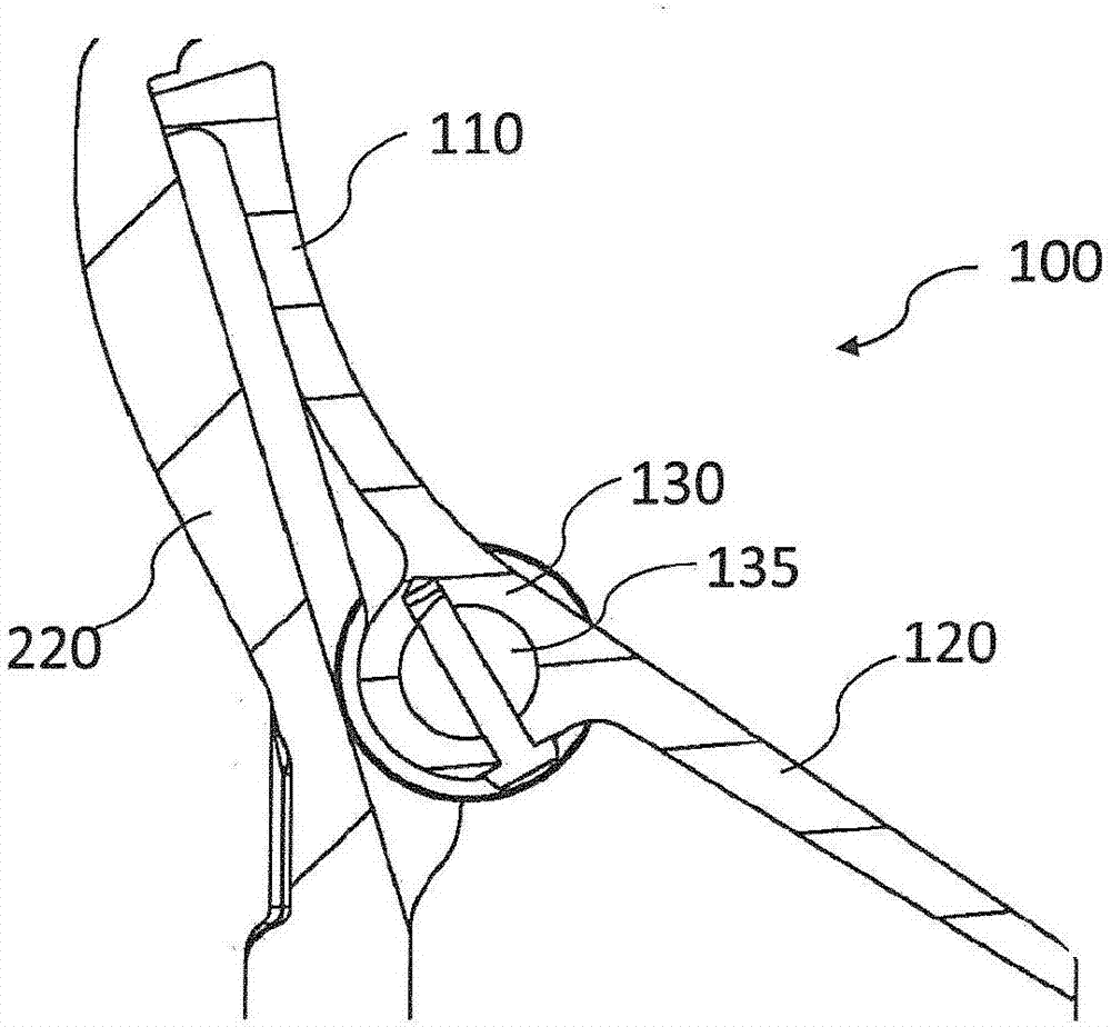
[0037] figure 1 A baffle 100 according to one embodiment of the application is shown. When placed in the exhaust system of a combustion engine, the baffle 100 is adapted to provide a valve that can be used to brake the vehicle by controlling the pressure of the exhaust flow. The baffle 100 includes a first arm part 110 , a second arm part 120 and a support part 130 disposed between the first arm part 110 and the second arm part 120 .

[0038] The support portion 130 is configured for mounting the baffle 100 rotatably about an axis of rotation 135 , wherein the axis of rotation 135 is arranged tangentially to the exhaust flow (in cross-sectional view). For example, if figure 1 The baffle 100 is shown mounted on a side wall 220 such that the axis of rotation 135 is tangential to the side wall.

[0039] The first arm portion 110 and / or the second arm portion 120 have a geometry such that the pressure acting on the first arm portion 110 is balanced with the pressure acting on...


PUM


Abstract

A flap (100) for braking a vehicle by controlling a pressure of a flow (105) of exhaust gas from a combustion engine (300) comprises: a first arm portion (110); a second arm portion (120); and a support portion (130). The support portion (130) is arranged be- tween the first arm portion (110) and the second arm portion (120). The support portion (130) is configured to mount the flap (100) rotatable about a rotational axis (135) being tangential in a cross-sectional view of the flow (105) of exhaust gas. The first arm portion (110) and the second arm portion (120) comprise a geometry to balance a pressure acting on the first arm portion (110) with the pressure acting on the second arm portion (120) to limit a maximal torque acting on the flap (100) about the rotational axis (135).

Description

technical field [0001] The present application relates to brake baffles, exhaust systems and in particular to pressure equalization baffles with different functions upstream of turbocharged turbines. Background technique [0002] Exhaust brakes slow vehicles, especially commercial vehicles, by closing off the exhaust path from a combustion engine so that the exhaust gas is compressed in the exhaust manifold and in the cylinders. As the exhaust is compressed, the engine slows the vehicle if no fuel is applied. The magnitude of the negative torque produced is generally proportional to the backpressure of the engine. [0003] A conventional exhaust system is eg described in EP 2679787, wherein an exhaust brake is arranged upstream of the turbocharger turbine and is integrated with the exhaust gas recirculation (EGR) supply port. Additionally, an exhaust pressure sensor is integrated to regulate EGR flow and engine mode performance by controlling the exhaust pressure upstream ...

Claims


Application Information

Patent Timeline
IPC IPC(8): F02B37/02F02B37/22F02B37/24F02D9/06F02M26/09F02M26/10
CPCF02B37/02F02B37/22F02B37/24F02D9/06F02M26/09F02M26/10Y02T10/12
Inventor H·内梅特A·尤哈斯Z·哲尔凯
Owner KNORR-BREMSE SYST FUER NUTZFAHRZEUGE GMBH
Why Eureka
Try Eureka