
Glass grabbing device and grabbing method

A glass and grasping unit technology, applied in the direction of manufacturing tools, chucks, program-controlled manipulators, etc., can solve the problems of production troubles, the inability to turn over the original glass sheet freely, etc., and achieve the effect of easy grasping

Active Publication Date: 2019-07-02
聊城市开发区信远信息科技有限公司
View PDF2 Cites 0 Cited by
  • Summary
  • Abstract
  • Description
  • Claims
  • Application Information

AI Technical Summary

Problems solved by technology

[0003] At present, the equipment commonly used for glass loading and unloading includes crane-vacuum suction cup combination device, automatic loading machine, and walking automatic loading machine. The adsorption force moves the original glass sheet, but due to the influence of the working environment, the original glass sheet can only have one surface for the suction cup to absorb, and the adsorption force needs to pass the center of gravity of the original glass sheet to ensure that the suction cup and the original glass sheet are tightly bonded, so that The original glass cannot be turned over freely by these devices, causing certain troubles in production

Method used


Image

  • Glass grabbing device and grabbing method
  • Glass grabbing device and grabbing method
  • Glass grabbing device and grabbing method

Examples


Embodiment 1

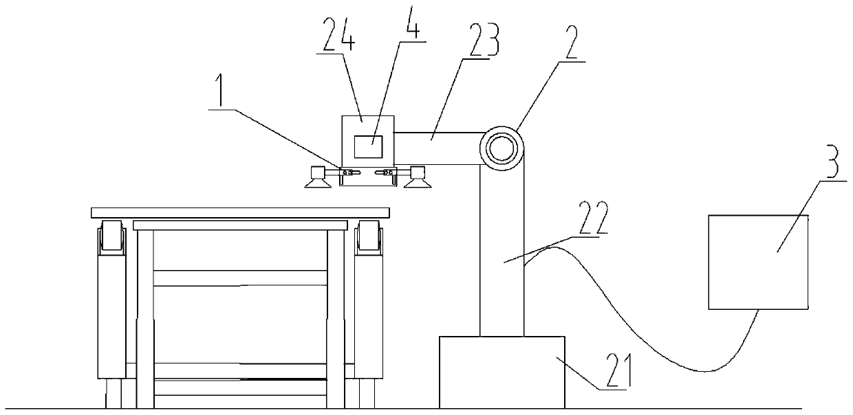
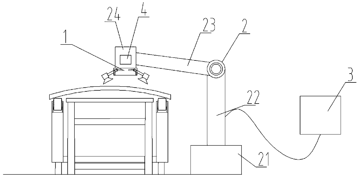
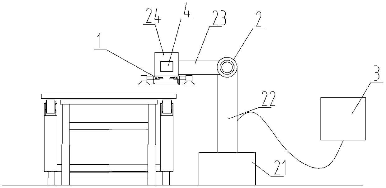
[0027] The invention relates to a glass grabbing device, the structural diagram of which is as follows figure 1 As shown, it includes a grabbing unit 1 , a moving unit 2 , a processing unit 3 , and an image capturing unit 4 .

[0028] The mobile unit 2 is fixed on the ground, the grasping unit 1 is fixedly connected with the mobile unit 2, the grasping unit 1 is used to grasp glass, and the mobile unit 2 is used to adjust the grasping unit 1; the image capture unit 4 is arranged on the capture unit 1, and the image capture unit 4 collects data such as the position of the original glass sheet, and transmits the data to the processing unit 3 The processing unit 3 is connected with the grabbing unit 1, the moving unit 2 and the image capturing unit 4 data, and the processing unit 3 processes the data collected by the image capturing unit 4, and the The moving unit 2 and the grabbing unit 1 issue instructions, and the moving unit 2 and the grabbing unit 1 perform grabbing operati...

Embodiment 2

[0034] The invention relates to a grabbing method for the glass grabbing device, the steps are specifically:

[0035] S1, read the data of the original glass sheet to be captured by the image capture unit 4, and transmit the data to the processing unit 3;

[0036] S2, through the calculation of the processing unit 3, control the moving unit 2 and the grabbing unit 1 to grab the original glass sheet;

[0037] S3, placing the original glass sheet at a designated position through the movement of the mobile unit 2;

[0038] Step S1 is specifically to move the grasping unit 1 to the position directly above the original glass sheet, the position is a fixed position, which is set by the processing unit 3, and generally is the transportation or support of the original glass sheet to be grasped. In the central position of the platform, a mesh pattern of square grids of equal size is set on the transport or support platform, the grid size is generally 5mmx5mm, the image capture device ...


PUM


Abstract

The invention discloses a glass grabbing device and a grabbing method. The glass grabbing device comprises a grabbing unit, a mobile unit, a processing unit and an image capture unit. The grabbing unit is fixed to the mobile unit fixedly arranged and used for freely moving the grabbing unit, and the image capture unit is arranged on the grabbing unit, and used for collecting the data of raw glass sheets; and the processing unit is in data connection with the grabbing unit, the mobile unit and the image capture unit, and used for processing data and controlling the movement of the grabbing unit, the mobile unit and the image capture unit. According to the glass grabbing device disclosed by the invention, the grabbing is more convenient and intelligent through collection of the relevant data of the image capture unit and the raw glass sheets as well as processing of the data with the processing unit.

Description

technical field [0001] The invention relates to the field of glass processing, in particular to a glass grabbing device and a grabbing method. Background technique [0002] In order to improve production efficiency, the specifications of the current types of processed glass tend to be larger, which leads to the need to use machinery to load the original glass sheets on the production line and unload the finished products from the production line, usually using a loading machine and unloading machine to achieve this operation. [0003] At present, the equipment commonly used for glass loading and unloading includes crane-vacuum suction cup combination device, automatic loading machine, and walking automatic loading machine. The adsorption force moves the original glass sheet, but due to the influence of the working environment, the original glass sheet can only have one surface for the suction cup to absorb, and the adsorption force needs to pass the center of gravity of the...

Claims


Application Information

Patent Timeline
IPC IPC(8): B25J15/00B25J9/16B25J15/06
CPCB25J9/1671B25J15/0033B25J15/0616
Inventor 胡翔
Owner 聊城市开发区信远信息科技有限公司
Learn More