
Gyrostabilized platform locking mechanism

A gyro-stabilized platform and locking technology, which is applied to aircraft parts, transportation and packaging, etc., can solve the problems of platform damage and impact on flight safety, and achieve the effect of improving impact resistance, reducing requirements, and small space

Inactive Publication Date: 2017-09-29
长春长光睿视光电技术有限责任公司
View PDF4 Cites 1 Cited by
  • Summary
  • Abstract
  • Description
  • Claims
  • Application Information

AI Technical Summary

Problems solved by technology

Both situations will cause certain damage to the platform, and even affect flight safety. Therefore, it is necessary to design a platform locking mechanism

Method used


Image

  • Gyrostabilized platform locking mechanism
  • Gyrostabilized platform locking mechanism
  • Gyrostabilized platform locking mechanism

Examples


Embodiment Construction

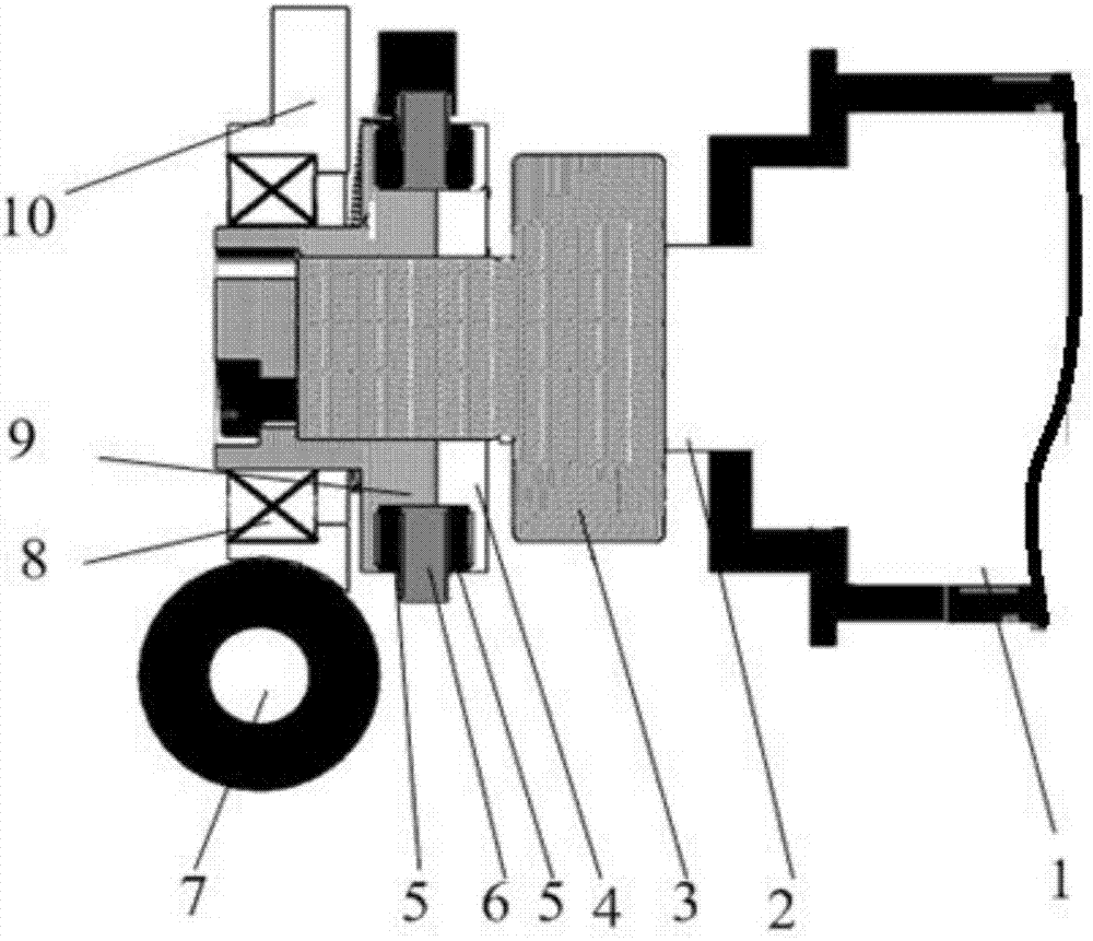
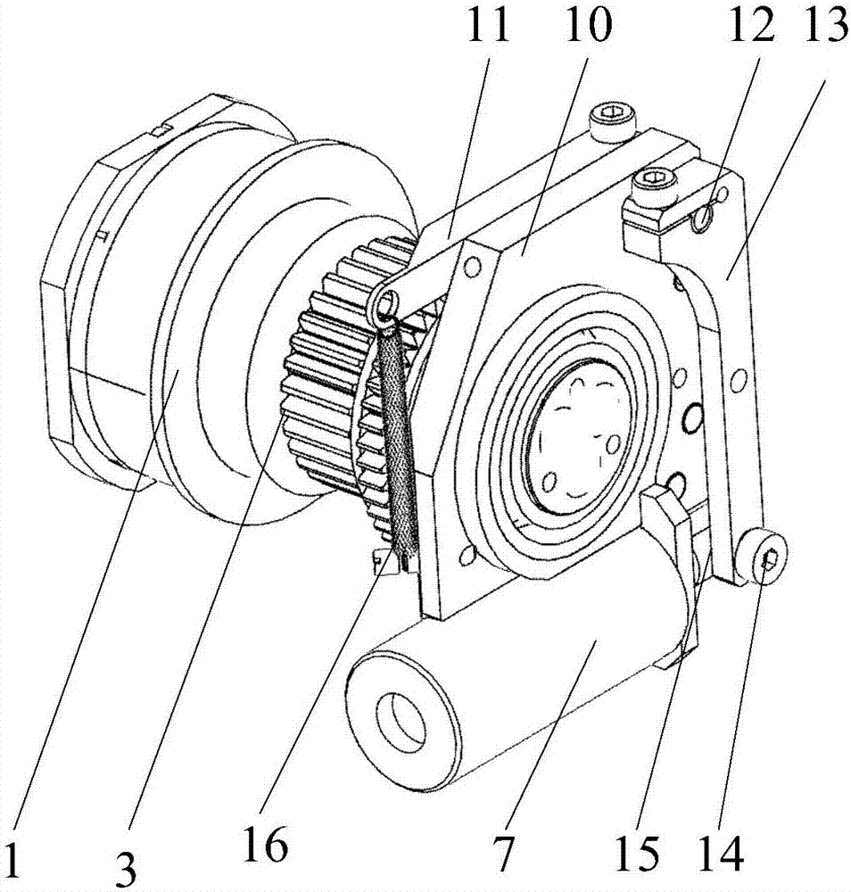
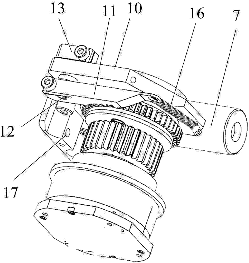
[0020] like figure 1 , 2 , shown in 3, the gyro-stabilized platform locking mechanism of the present invention comprises base 10, electromagnet 7, connecting rod 13, locking rack 11, back-moving spring 16, locking gear 6, buffer rubber 5, 1 fixing ring 9 and II retaining ring 4. see figure 1 , the drive gear 3 is installed on the drive unit output shaft 2, the I fixed ring 9 is connected with the base 10 through the output shaft bearing 8, and the left end face of the I fixed ring 9 is fixedly connected with the gear shaft of the drive gear 3 by a screw 18; I is fixed Ring 9 and II fixed ring 4 are sleeved on the gear shaft of drive gear 3, II fixed ring 4 is located on the right side of I fixed ring 9 and I fixed ring 9 and II fixed ring 4 are fixed together by bolt connection; lock the gear 6. Adhesive buffer rubber 5 on both sides; locking gear 6 and two pieces of buffer rubber 5 are clamped together between I fixing ring 9 and II fixing ring 4, and two pieces of buffer ...


PUM


Abstract

The invention relates to a gyrostabilized platform locking mechanism. A fixing ring I of the gyrostabilized platform locking mechanism is connected with a base through an output shaft bearing; the fixing ring I and a fixing ring II are installed in a sleeving mode and are fixed on a gear shaft of a drive gear, the fixing ring II is located at the right side of the fixing ring I and the fixing ring I, and the fixing ring II are fixed together; a locking gear is firmly clamped and fixed between the fixing ring I and the fixing ring II; the base is fixedly connected with an outer frame; a locking rack is meshed with the locking gear, one end of the locking rack is fixedly connected with a rotation shaft, and the other end of the locking rack is connected with a reset spring. The other end of the reset spring is connected with the base; the rotation shaft is mounted at the upper portion of the base and can rotate round the base; a connecting rod is located at the other side, opposite to the locking rack, of the base, and the upper end of the connecting rod is fixedly connected with the rotation shaft; a sliding groove is formed in the lower end of the connecting rod, and a circular shaft is fixed on an electromagnet motion iron score and located in the sliding groove and can slide along the sliding groove. According to the gyrostabilized platform locking mechanism, through the locking gear shaft, the effect of locking a platform axial system is achieved. The gyrostabilized platform locking mechanism has the advantages of being light in weight and small in required space.

Description

Technical field: [0001] The invention belongs to the technical field of aviation equipment mechanical structure, and in particular relates to a locking mechanism of a gyro-stabilized platform. Background technique: [0002] The gyro-stabilized platform provides vertical photography and image motion compensation capabilities for aerial remote sensing. Bias current compensation is performed through the setting of the real track and the expected track, reducing the risk of insufficient overlap between images and improving operational efficiency. [0003] A gyro-stabilized platform in the prior art includes a drive unit, a drive gear, a ring gear, an inner frame, an outer frame and platform bearings. The inner ring of the platform bearing is connected with the inner frame, and the outer ring is connected with the outer frame. The driving gear is installed on the output shaft of the driving unit, and the casing of the driving unit is connected with the outer frame. The ring gea...

Claims


Application Information

Patent Timeline
Patent Type & Authority Applications(China)
IPC IPC(8): B64D47/00
CPCB64D47/00
Inventor 聂品惠守文马秋瀚唐博于跃
Owner 长春长光睿视光电技术有限责任公司
Learn More