Clamping pin, manufacturing method thereof, aluminum alloy template system using clamping pin and construction method

A manufacturing method and formwork technology, which is applied to the joints of formwork/formwork/work frame, formwork/formwork components, building structures, etc., can solve problems such as high cost, unguaranteed precision, loose screws, etc., and achieve construction Fast progress, improved wall appearance, and cost-saving effects

Pending Publication Date: 2017-09-29
SHANDONG XINHUOXIN MATERIAL TECH CO LTD
View PDF6 Cites 3 Cited by
  • Summary
  • Abstract
  • Description
  • Claims
  • Application Information

AI Technical Summary

Problems solved by technology

The vast majority of aluminum formwork on the market adopts the traditional pull-screw formwork system, which requires one-time auxiliary materials such as cement fixing columns, steel fixing columns or screw sleeves for each floor slab, and the cost is too high
In addition, there are problems such as the tightness and looseness of the screw and the loosening of the vibrating rod after the vibration of the pull screw, and the accuracy cannot be guaranteed.

Method used


Image

  • Clamping pin, manufacturing method thereof, aluminum alloy template system using clamping pin and construction method
  • Clamping pin, manufacturing method thereof, aluminum alloy template system using clamping pin and construction method
  • Clamping pin, manufacturing method thereof, aluminum alloy template system using clamping pin and construction method

Examples


Embodiment Construction

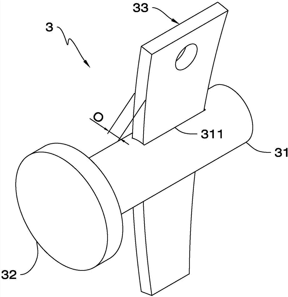
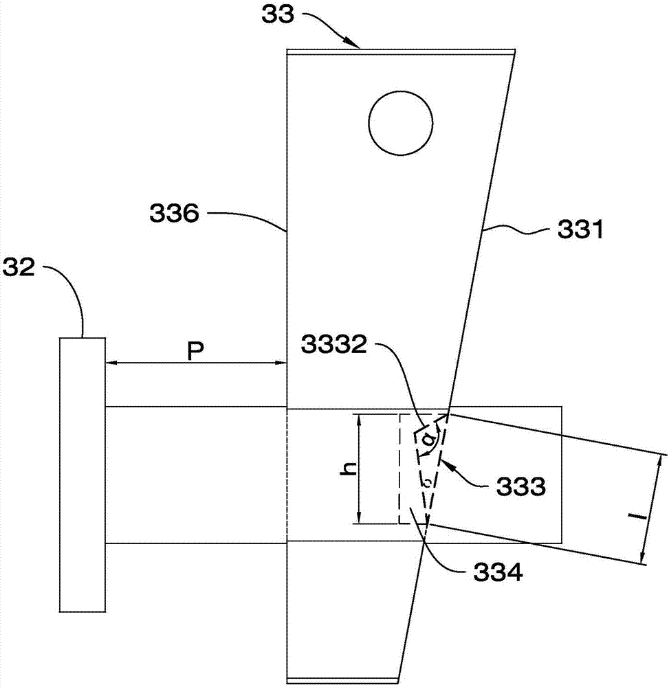
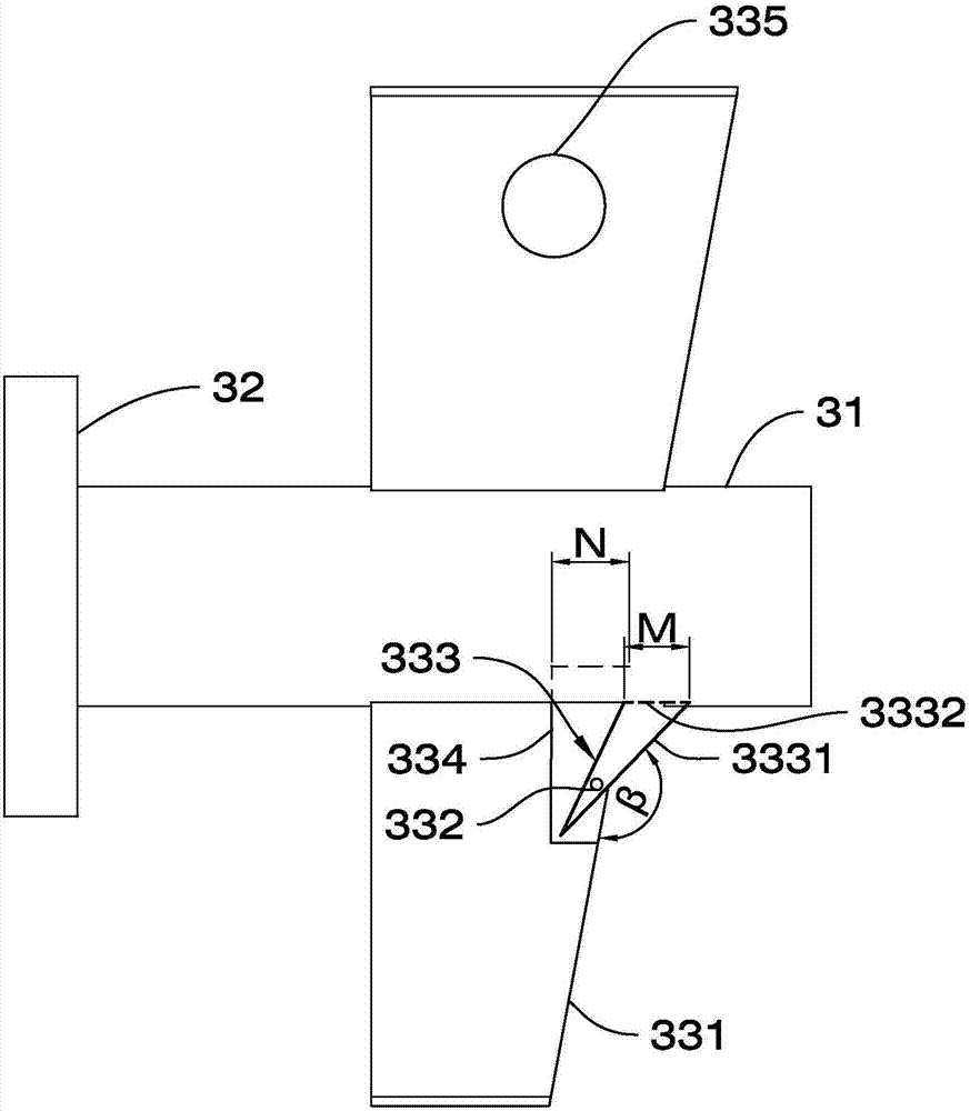
[0043] Such as Figure 1 to Figure 10 As shown, the detent 3 includes a pin body 31, a head 32 and a spacer 33, wherein the pin body 31 is conical, the spacer 33 is a right-angled trapezoid, and the pin body 31 is provided with a shape corresponding to the spacer 33. Compatible limit hole 311, the limit piece 33 can be partially inserted in the limit hole 311 and the maximum width of the limit piece 33 is greater than the maximum aperture of the limit hole 311, the limit piece 33 can be inserted from one end of the limit hole 311 Enter and exit. Specifically, the limiting piece 33 is an arc-shaped bent plate with a wide upper end and a narrow lower end, and the limiting hole 311 is also arc-shaped matching it. The narrow end of the arc-shaped bent plate is inserted downward into the limit hole 311, and the part inserted into the limit hole 311 on the limit piece 33 fits with the hole wall of the limit hole 311. At the same time, because the maximum width of the limit piece 33...


PUM


Abstract

The invention relates to a clamping pin, a manufacturing method thereof, an aluminum alloy template system using the clamping pin and a construction method, and aims to provide a clamping pin, a manufacturing method thereof, an aluminum alloy template system by the clamping pin and a matched construction method, wherein the clamping pin is simple in structure, convenient to disassemble and assemble and good in fixing effect, and the aluminum alloy template system has high supporting stability. A limit hole is formed in a conical pin body, and a right-angled trapezoid limit piece can enter and exit the limit hole. When the clamping pin is manufactured, the conical pin body and a circular head are firstly formed, the limit hole and the limit piece are formed, the limit piece can enter and exit the limit hole, concrete is poured between an inner template and an outer template of the aluminum alloy template system, and the edges of the inner template and the outer template are connected through the clamping pin and a pull piece. When construction is performed, the inner template and the outer template are firstly arranged, the pull piece is connected with the inner template and the outer template through the clamping pin, the concrete is poured, the clamping pin, the inner template and the outer template are disassembled after the concrete solidifies, and the pull piece positioned outside the concrete is broke off. The clamping pin is simple in structure, convenient to disassemble and assemble and good in fixing effect, the aluminum alloy template system using the clamping pin is high in supporting stability, and the construction method is matched with the system.

Description

technical field [0001] The invention relates to the technical field of aluminum formwork construction, in particular to a bayonet pin and a manufacturing method thereof, an aluminum alloy formwork system and a construction method using the same. Background technique [0002] Aluminum alloy formwork is widely used in the construction industry due to its advantages of saving plastering costs, high recycling value and reusability. The vast majority of aluminum formwork on the market adopts the traditional pull-screw formwork system, which requires one-time auxiliary materials such as cement fixing columns, steel bar fixing columns or screw sleeves for each floor slab, and the cost is too high. Moreover, there are problems such as the tightness and looseness of the screw and the loosening of the vibrating rod after the vibration of the pull screw, so the accuracy cannot be guaranteed. At the same time, in order to meet the high requirements of developers and general contractors...

Claims


Application Information

Patent Timeline
Patent Type & Authority Applications(China)
IPC IPC(8): E04G17/04E04G9/06
CPCE04G9/06E04G17/047
Inventor 马仁怀林松山仲少军丁周庆王恒磊魏庆传
Owner SHANDONG XINHUOXIN MATERIAL TECH CO LTD
Why Eureka
Try Eureka