
A sliding limit type kiln outlet plugging system

A discharge opening and position limiting technology, which is applied in the field of sliding limit kiln discharge opening blockage system, can solve problems such as poor sealing, inconvenient operation, and hidden dangers to the safety of operators, so as to achieve large blocking thrust and easy operation. Convenience, strong sealing effect

Active Publication Date: 2019-01-11
济宁高新产业园运营管理有限公司
View PDF5 Cites 0 Cited by
  • Summary
  • Abstract
  • Description
  • Claims
  • Application Information

AI Technical Summary

Problems solved by technology

[0004] The technical problem to be solved by the present invention is to provide a sliding limit type kiln outlet plugging system with simple and practical structure and easy operation. The seal is not tight, which poses a hidden danger to the safety of operators

Method used


Image

  • A sliding limit type kiln outlet plugging system
  • A sliding limit type kiln outlet plugging system
  • A sliding limit type kiln outlet plugging system

Examples


Embodiment

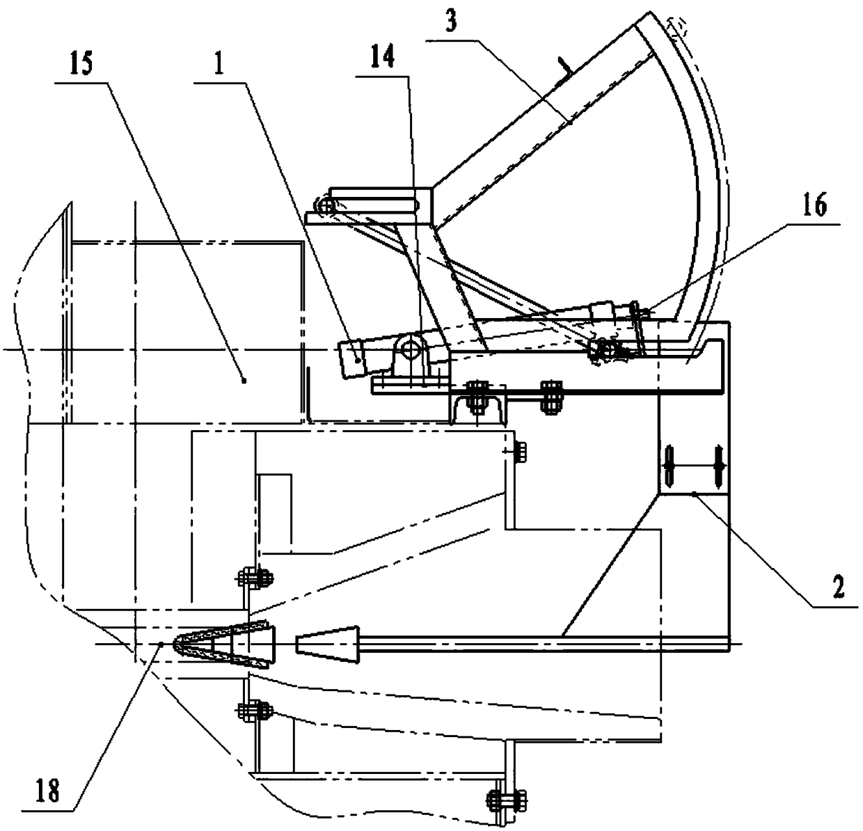
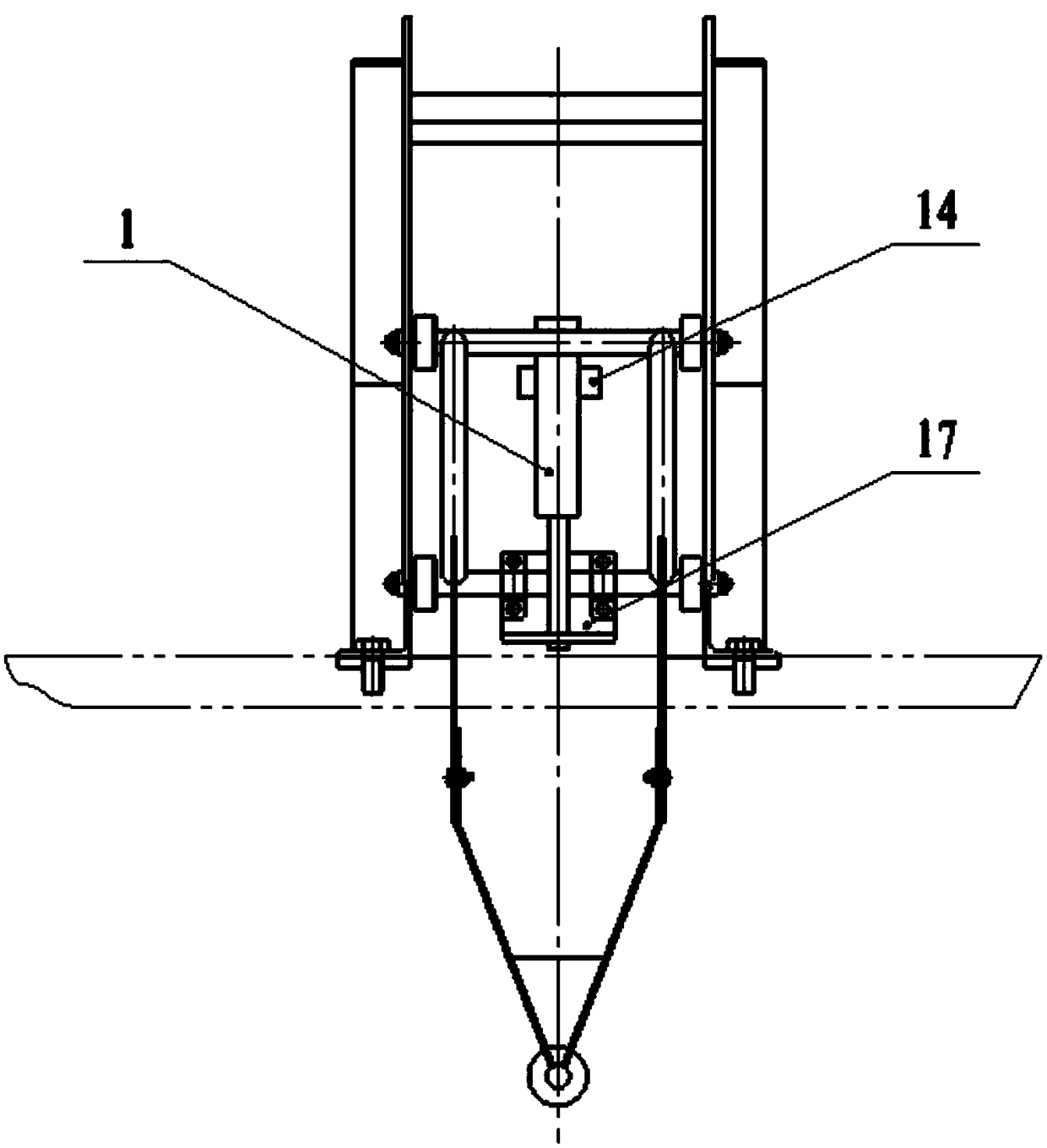
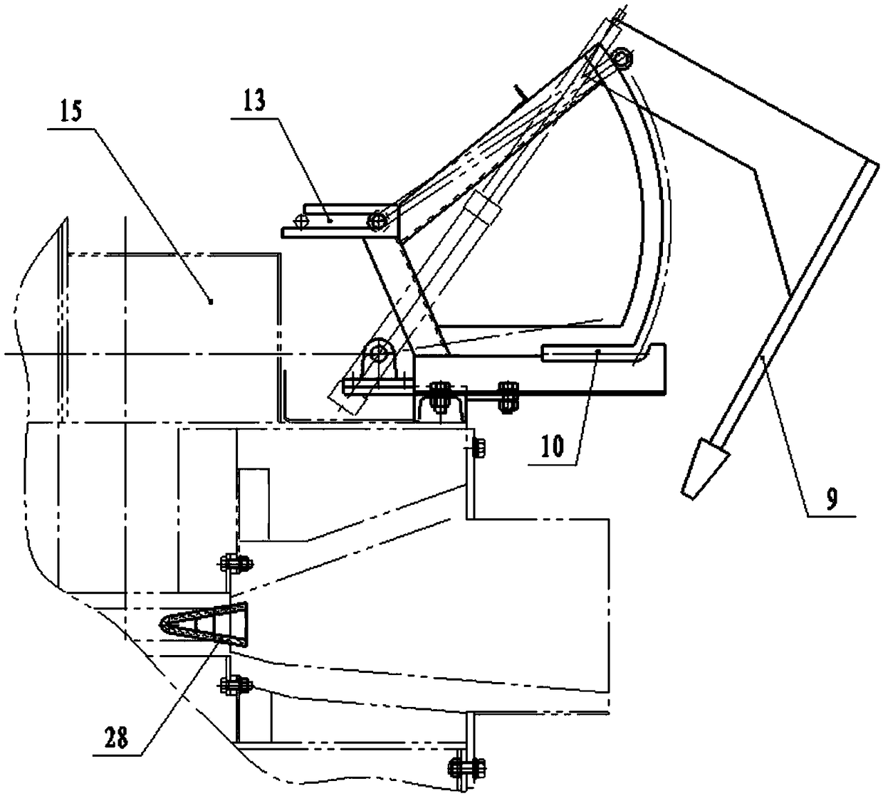
[0029] like Figure 1-7 The blockage system for the discharge port of a sliding limit type kiln shown includes a cylinder 1, a plug assembly 2 and a slide rail assembly 3, the plug assembly 2 is a movable part, the slide rail assembly 3 is a stationary part, and the plug assembly 2 Under the action of the cylinder 1, the blockage or opening of the discharge port 18 is realized through the limit and guidance of the slide rail assembly 3, such as Figure 4-5 As shown, the plug head assembly 2 includes an L-shaped plug rod 4 and a plug rod frame-shaped bracket 5, the front end of the plug rod frame-shaped bracket 5 is provided with a front connecting shaft 6, and the rear end of the plug rod frame-shaped bracket 5 is provided with a rear connecting shaft 7. The upper end of the L-shaped plug rod 4 is a U-shaped bracket 8, the lower end of the L-shaped plug rod 4 is a plug rod 9, and the L-shaped plug rod 4 is connected to the plug rod frame-shaped bracket through the U-shaped bra...


PUM


Abstract

The invention discloses a sliding limiting type kiln discharging outlet plugging system. The system comprises an air cylinder, a chock plug assembly and a sliding rail assembly. The air cylinder is mounted on a furnace body through an air cylinder mounting seat, an air cylinder arm of the air cylinder is connected with a front connecting shaft of a plug rod frame type support through an air cylinder head mounting frame, and the sliding raid assembly corresponds to the air cylinder and is also fixed to the furnace body. The two end heads of the front connecting shaft are slidably mounted in a front horizontal sliding groove, and the two end heads of a rear connecting shaft are slidably mounted in a rear horizontal sliding groove. Compared with an existing discharging outlet plugging system, according to the plugging system, the plugging success rate reaches 99% or more, and through multi-time tests, under correct operation, no liquid leakage phenomenon occurs.

Description

technical field [0001] The invention relates to the field of supporting devices for smelting non-ferrous metals, and in particular relates to a blocking system for a sliding limit type kiln outlet. Background technique [0002] At present, the furnace body of the metal melting furnace is welded by steel plates and section steel, and is equipped with its own burner. There is a liquid metal circulation channel between the melting room and the heat preservation room. When working, the molten metal is continuously flowing from the melting room After flowing into the heat preservation room, the molten metal flowing into the heat preservation room is heated up to the operating temperature in the heat preservation room, and the refractory mud at the discharge port is manually opened for discharge. [0003] In addition, the discharge port of the metal melting furnace is generally made of refractory cement or graphite material, and is often blocked by a metal plug with an asbestos pa...

Claims


Application Information

Patent Timeline
Patent Type & Authority Patents(China)
IPC IPC(8): F27D3/15
CPCF27D3/1536F27M2003/13
Inventor 李永芬
Owner 济宁高新产业园运营管理有限公司
Learn More