Three-dimensional laser radar based on MEMS scanning micro-mirror, range finding method

A micro-scanning mirror, three-dimensional laser technology, applied in measurement devices, re-radiation of electromagnetic waves, radio wave measurement systems, etc., can solve the problems of small scanning field of view, low refresh rate, complex structure of lidar, etc. , long detection distance, simple structure effect

Active Publication Date: 2017-09-29
XI AN ZHISENSOR TECH CO LTD
View PDF7 Cites 51 Cited by
  • Summary
  • Abstract
  • Description
  • Claims
  • Application Information

AI Technical Summary

Problems solved by technology

[0007] Aiming at the shortcomings of existing laser radar based on two-axis MEMS micro-scanning mirror, which has a complex structure, a small scanning field of view, and a low refresh rate, the present invention provides a three-dimensional laser radar and a ranging method based on a MEMS micro-scanning mirror , usi...

Method used


Image

  • Three-dimensional laser radar based on MEMS scanning micro-mirror, range finding method
  • Three-dimensional laser radar based on MEMS scanning micro-mirror, range finding method
  • Three-dimensional laser radar based on MEMS scanning micro-mirror, range finding method

Examples


Embodiment Construction

[0040] The present invention will be further described below in conjunction with the accompanying drawings. It should be noted that this embodiment is based on the technical solution and provides detailed implementation and specific operation process, but the protection scope of the present invention is not limited to this embodiment. example.

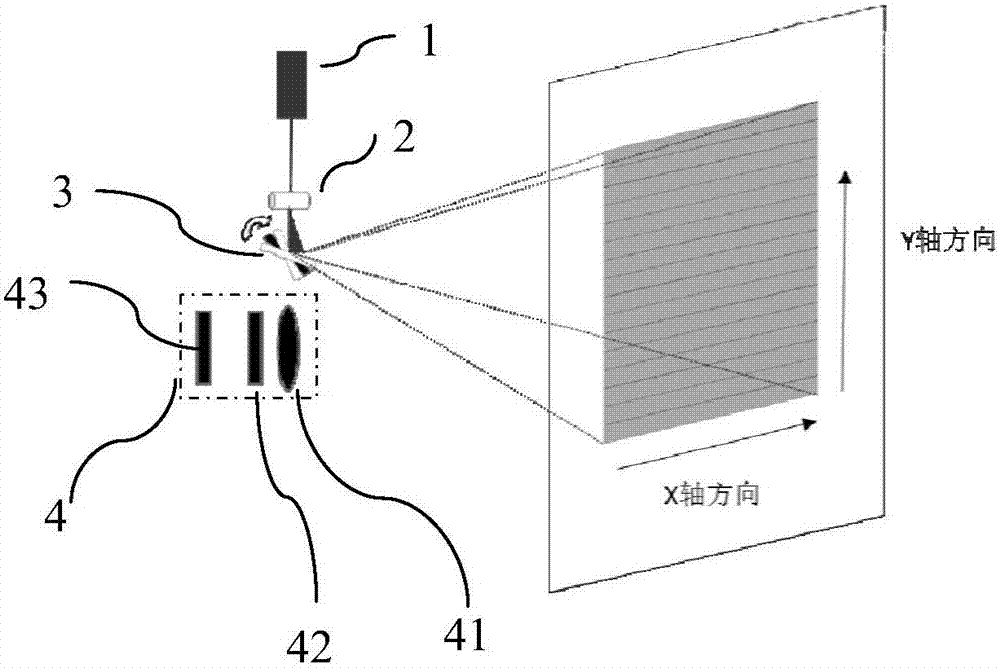
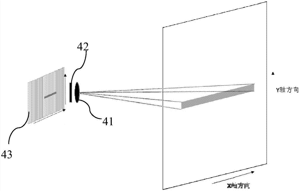
[0041] see figure 1 The three-dimensional laser radar based on the MEMS micro-scanning mirror provided by the present invention includes a laser emitting device, a laser scanning device, a laser receiving device 4, a driving circuit and a signal processing circuit.

[0042] The laser scanning device is arranged on the output optical path of the laser emitting device, and the laser receiving device 4 and the laser emitting device are located on the same side of the target to be measured; the laser emitting device and the photodetector are as close as possible and relatively fixed in position; the laser receiving device 4 The field of vie...


PUM


Abstract

The invention provides a three-dimensional laser radar based on a MEMS scanning micro-mirror and a range finding method in view of the complex structure, the small scanning field of view, and the low refresh rate of a conventional laser radar based on a double-axis MEMS scanning micro-mirror. A single-axis MEMS scanning micro-mirror and an optical component with a one-dimensional amplification function are used in cooperation to realize two-dimensional surface scanning. A photoelectric detector composed of a linear detection unit is used for achieving laser echo detection. The three-dimensional laser radar is simple in structure, large in scanning field of view, and high in refresh rate.

Description

technical field [0001] The invention belongs to the field of laser radar, and relates to a three-dimensional laser radar based on a MEMS micro-scanning mirror and a ranging method. Background technique [0002] Unmanned driving technology requires cars to be able to understand the complex traffic conditions in reality, and to be as flexible as human eyes and brains. The key to realizing autonomous driving capability is that various sensors need to cooperate and transmit the monitored data to a high-precision processor to identify roads, signs and pedestrians, so as to make decisions such as acceleration, steering and braking. [0003] At present, there are three mainstream sensors used to sense the surrounding environment: camera vision sensor, ordinary millimeter-wave radar and lidar. The camera vision sensor can easily realize high-resolution images, but it is easily affected by environmental factors (such as light intensity) and external factors, and it must rely on powe...

Claims


Application Information

Patent Timeline
IPC IPC(8): G01S17/08
CPCG01S17/08
Inventor 游桥明刘义松张雅男夏长锋乔大勇
Owner XI AN ZHISENSOR TECH CO LTD
Why Eureka
Try Eureka