Power distribution control cabinet convenient to mount and maintain

A convenient installation and control cabinet technology, which is applied in the substation/distribution device casing, cooling/ventilation of substation/switchgear, electrical components, etc., can solve the problem of lower sensitivity of control instruments, difficulty in dissipating heat from the housing, power supply lines, etc. Aging short circuit and other problems, to achieve the effect of easy inspection and maintenance, improve heat dissipation effect, and improve efficiency

Inactive Publication Date: 2017-09-29
DONGYING SHENGLI ZHENGDA ELECTRIC POWER EQUIPCO
View PDF9 Cites 0 Cited by
  • Summary
  • Abstract
  • Description
  • Claims
  • Application Information

AI Technical Summary

Problems solved by technology

[0002] At present, the control cabinets in the power supply distribution room and the control cabinets in the automatic power distribution room rely on exhaust fans to draw air and dissipate heat. Since the control cabinet shell is tightly closed, the heat in the shell is not easy to dissipate, especially for control cabinets with relatively large power. The heat is not easy to dissipate, especially in summer, the temperature in the control cabinet is as high as 60 degrees, which makes the power supply line aging and short circuit, the sensitivity of the control instrument is reduced, and a large amount of maintenance workload is increased.
In addition, the current control cabinet only has the front door, and the rear is the sealing plate on the screw. Due to the complicated power supply line, it is particularly difficult to check and maintain the front, rear, left, and right sides.

Method used


Image

  • Power distribution control cabinet convenient to mount and maintain

Examples


Embodiment Construction

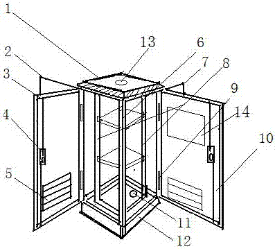
[0016] In order to further disclose the technical solution of the present invention, the following will be described in detail through the embodiments in conjunction with the accompanying drawings:

[0017] The present invention comprises a cabinet body frame 6, an equipment installation frame 8, an upper top 1 and a lower bottom, and a hinge frame or a hinge-connected control cabinet door that limits the opening degree of the door is respectively provided on the front, rear, left, and right frames of the cabinet body frame, Including the back door 2 of the control cabinet, the left door 3 of the control cabinet, the right door 7 of the control cabinet and the front door 10 of the control cabinet, a handle latch switch mechanism 4 is provided on the other side of the control cabinet door, and a The louver type ventilation window; the upper top is provided with a wind flow case with a lower opening and a top cap, an exhaust hole is arranged around the side of the wind flow case,...


PUM


Abstract

The invention discloses a power distribution control cabinet convenient to mount and maintain, which comprises a cabinet body frame, a device mounting frame, control cabinet doors, ventilation blinds, a top, an air flow fan and a bottom, and is characterized in that each of front, rear, left and right frames of the cabinet body frame is provided with a hinge bracket for limiting the opening degree of the door or one control cabinet door connected by a hinge; the middle part of the top is provided with the air flow fan; a rectangular base with a lower opening is arranged below the bottom; the rectangular base and the bottom are provided with concentric cable holes; the device mounting frame formed by four supports is arranged between the top and the bottom inside the cabinet body frame; symmetrical mounting plate insertion holes are arranged in the device mounting frame; and mounting plates are arranged on the insertion holes. The power distribution control cabinet convenient to mount and maintain has the advantages of convenient cooling, convenient maintenance, saved maintenance time and safe maintenance.

Description

technical field [0001] The invention relates to a power distribution control cabinet convenient for installation and maintenance, which solves the problems of difficult heat dissipation and inconvenient installation and maintenance of the existing power distribution control cabinet. Background technique [0002] At present, the control cabinets in the power supply distribution room and the control cabinets in the automatic power distribution room rely on exhaust fans to draw air and dissipate heat. Since the control cabinet shell is tightly closed, the heat in the shell is not easy to dissipate, especially for control cabinets with relatively large power. The heat is not easily dissipated, especially in summer, when the temperature in the control cabinet is as high as 60 degrees, which makes the power supply line aging and short circuit, the sensitivity of the control instrument is reduced, and a large amount of maintenance workload is increased. In addition, the current con...

Claims


Application Information

Patent Timeline
Patent Type & Authority Applications(China)
IPC IPC(8): H02B1/56H02B1/30
CPCH02B1/30H02B1/565
Inventor 杨宁刘志涛刘玉秀孙晓云魏杰于凤玲
Owner DONGYING SHENGLI ZHENGDA ELECTRIC POWER EQUIPCO
Why Eureka
Try Eureka