Switch installation shell

A switch and shell technology, which is applied in the field of network communication equipment, can solve problems such as affecting the heat dissipation of the switch, easily damaging the switch, and affecting the beauty and so on.

Inactive Publication Date: 2017-09-29
南宁市正祥科技有限公司
View PDF0 Cites 0 Cited by
  • Summary
  • Abstract
  • Description
  • Claims
  • Application Information

AI Technical Summary

Problems solved by technology

The existence of the switch brings great convenience to the network. The placement of the switch is also very important. Usually we place the switch on the

Method used


Image

  • Switch installation shell

Examples


Embodiment Construction

[0009] Specific embodiments of the present invention will be described below.

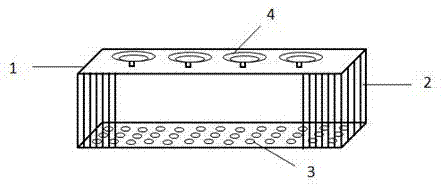
[0010] Such as figure 1 As shown, a switch placement shell, including a shell 1, is characterized in that: the two sides of the shell 1 are provided with strip-shaped air holes 2; the bottom surface of the shell 1 is provided with a circular air hole 3; the shell A suction cup 4 is provided on the top surface of the body 1; an opening is provided on the front of the housing 1.

[0011] The switch placement case of the present invention has good heat dissipation performance, and the switch placement case can be fixed on the bottom of the table or a relatively hidden place through the suction cup provided on the top surface of the case, which neither occupies the ground space nor affects the indoor appearance, and is very practical.

[0012] The above is only a preferred embodiment of the present invention, but the scope of protection of the present invention is not limited thereto, any person fami...


PUM


Abstract

The invention discloses a housing for an exchange, which includes a housing, and is characterized in that: strip-shaped ventilation holes are provided on both sides of the housing; circular ventilation holes are provided on the bottom surface of the housing; the top surface of the housing A suction cup is provided; the front of the housing is provided with an opening. The switch placement shell of the present invention has good heat dissipation performance, and the switch placement shell can be fixed on the bottom of the table or a relatively hidden place through the suction cup provided on the top surface of the shell, which neither occupies the ground space nor affects the indoor appearance, and is very practical.

Description

technical field [0001] The invention relates to a network communication device, in particular to an exchange housing. Background technique [0002] A switch is a network device used for electrical signal forwarding. It can provide an exclusive electrical signal path for any two network nodes connected to the switch. The switch has multiple ports, and each port has a bridging function, which can be connected to a local area network or a high-performance server or workstation. The existence of the switch brings great convenience to the network, and the placement of the switch is also very important. Usually, we place the switch on the ground at will. This placement method not only affects the beauty but also affects the heat dissipation of the switch, and it is easy to damage the switch. Contents of the invention [0003] The purpose of the present invention is to provide a switch placement case to solve the above-mentioned multiple defects in the prior art. [0004] The ...

Claims


Application Information

Patent Timeline
IPC IPC(8): H04L12/931
CPCH04L49/10
Inventor 不公告发明人
Owner 南宁市正祥科技有限公司
Why Eureka
Try Eureka