Supercharge Your Innovation With Domain-Expert AI Agents!

Inert gas auxiliary ejection lens mold ejection structure and ejection method

A technology of inert gas and lens molds, which is applied in household appliances, other household appliances, optical components, etc., can solve problems affecting the dimensional accuracy of injection molding products, cumbersome gas path settings, complex structures, etc., to achieve ingenious design, quality assurance, and guarantee The effect of optical properties

Pending Publication Date: 2017-10-03
HASCO VISION TECHNOLOGY CO LTD
View PDF8 Cites 0 Cited by
  • Summary
  • Abstract
  • Description
  • Claims
  • Application Information

AI Technical Summary

Problems solved by technology

This kind of structural form that uses multiple ejector pins to ventilate, the structure is more complicated, the air path setting is more cumbersome, and the multiple air path channels will also affect the dimensional accuracy of the injection molding product, which is completely unsuitable for lens injection molding production.

Method used


Image

  • Inert gas auxiliary ejection lens mold ejection structure and ejection method
  • Inert gas auxiliary ejection lens mold ejection structure and ejection method
  • Inert gas auxiliary ejection lens mold ejection structure and ejection method

Examples


Embodiment Construction

[0025] The present invention will be further described below in conjunction with the accompanying drawings and specific embodiments.

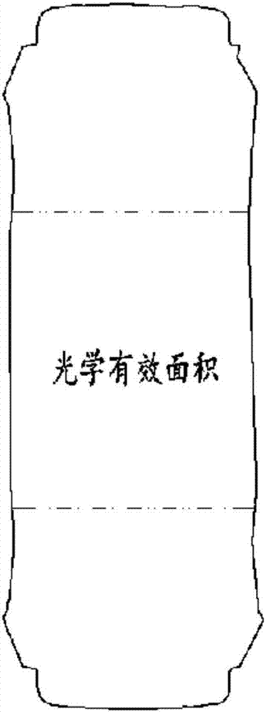
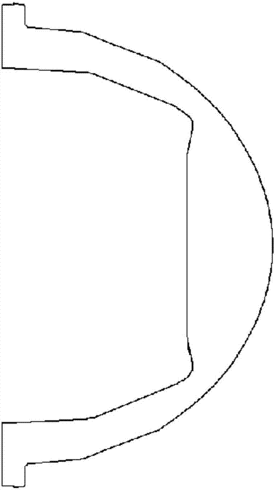
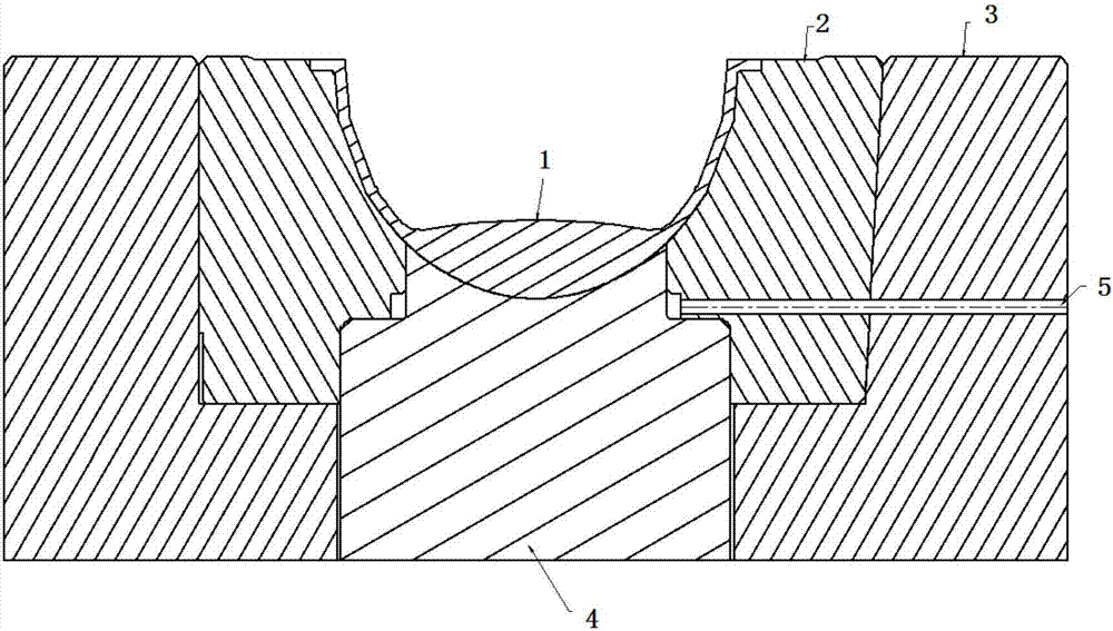
[0026] see Figure 1-6 , a lens mold ejection structure assisted by an inert gas, comprising a first movable mold insert 4 corresponding to the optical effective area of ​​the lens, a second movable mold insert 2 corresponding to the peripheral position of the lens; the second movable mold insert 2 The mold insert 2 has an inert gas vent hole 5 communicating with the outside, and the inert gas vent hole 5 leads from the outside to the annular junction 6 of the second movable mold insert 2 and the first movable mold insert 4, and the annular The junction part 6 communicates with the bottom of the lens 1 through the annular gap 7 between the first movable mold insert 4 and the second movable mold insert 2; the size of the annular gap 7 is smaller than the size that the injection molding material can pass through, and larger than the inert gas pa...


PUM


Abstract

The invention relates to an inert gas auxiliary ejection lens mold ejection structure. The structure comprises a first movable die insert and a second movable die insert, wherein the first movable die insert corresponds to the lens optical effective area, and the second movable die insert corresponds to the peripheral position of a lens. The second movable die insert is provided with an inert gas vent hole communicated with the exterior, the inert gas vent hole leads to the annular juncture portion of the second movable die insert and the first movable die insert from the outer portion, the annular juncture portion is communicated with the bottom of the lens through the annular gap between the first movable die insert and the second movable die insert, and the size of the annular gap is smaller than the size of the portion where an injection material can pass through, and is larger than the size of the portion where the inert gas can pass through. The inert gas vent hole is formed in a die so as to avoid the vacuum condition appearing after product forming, the condition of breaking of the product in the ejection process is avoided, in the ejection process, the lens product cannot be damaged, and the lens product optical property is ensured.

Description

technical field [0001] The invention relates to a lens mold, in particular to a lens mold ejection structure assisted by an inert gas, and belongs to the technical field of lens manufacturing. Background technique [0002] Lens products have optical performance requirements. During the molding process, the ejection and pickup must be performed after the injection molding is full, so as to ensure the optical performance of the product. After the product is fully injected, it is often caused by the vacuum formed in the cavity of the mold, resulting in the failure of the product to be ejected. [0003] The date of authorization announcement is CN206170540U, and the date of announcement is the Chinese patent document on May 17, 2017. It discloses an injection mold and its ejection mechanism. A ventilation pipe for connecting with an external air pump is arranged in the thimble. For the air outlet of the air outlet, when demolding, first slowly pass air to the ventilation pipe f...

Claims


Application Information

Patent Timeline
IPC IPC(8): B29C45/43B29L11/00
CPCB29C45/43B29L2011/00
Inventor 魏霓宋洁明崔凯苗蓓蕾
Owner HASCO VISION TECHNOLOGY CO LTD
Features
  • R&D
  • Intellectual Property
  • Life Sciences
  • Materials
  • Tech Scout
  • Unparalleled Data Quality
  • Higher Quality Content
  • 60% Fewer Hallucinations
Learn More