A Programmable Plasma Dielectric Antenna

A plasma and dielectric antenna technology, applied to antennas, devices that enable antennas to work in different bands at the same time, resonators, etc., can solve the problems of high dielectric constant of materials, congestion of frequency band resources, expensive prices, etc., and achieve wide application prospects , Simple structure and strong function

Active Publication Date: 2019-05-17
NANJING UNIV OF POSTS & TELECOMM +1
View PDF3 Cites 0 Cited by
  • Summary
  • Abstract
  • Description
  • Claims
  • Application Information

AI Technical Summary

Problems solved by technology

At the same time, in order to ensure the quality of communication, it is necessary to solve the congestion of existing frequency band resources and the interference between antennas
[0003] However, the dielectric antenna has the following disadvantages: first, its Q value will increase with the increase of the material permittivity, which will reduce the bandwidth of the antenna, so the dielectric resonant antenna will limit its operating bandwidth; secondly, due to the dielectric The size of the antenna is small, so it requires high processing technology and is not easy to tune. The dielectric constant of the material is relatively high, so the price is relatively expensive

Method used


Image

  • A Programmable Plasma Dielectric Antenna
  • A Programmable Plasma Dielectric Antenna
  • A Programmable Plasma Dielectric Antenna

Examples


Embodiment Construction

[0019] The present invention will be described in further detail below in conjunction with the accompanying drawings.

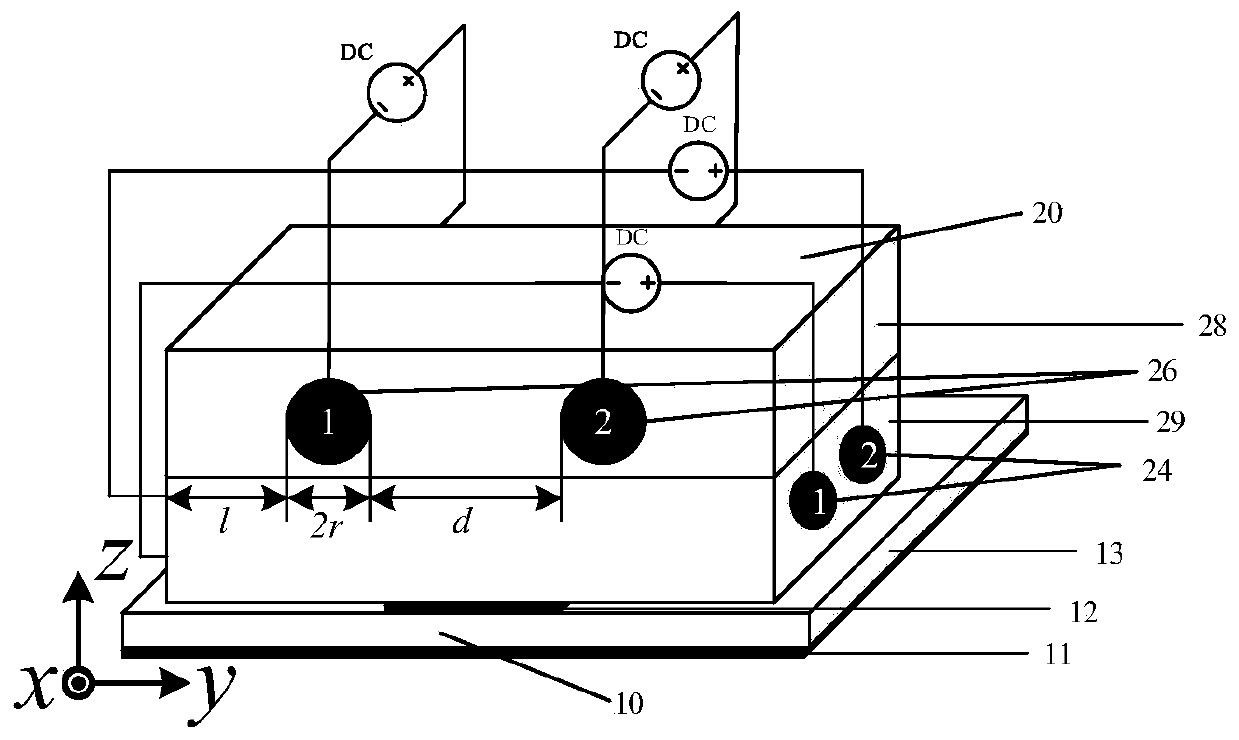
[0020] Such as figure 1 As shown, it is a schematic structural diagram of a programmable plasma dielectric antenna according to an embodiment of the present invention. A programmable plasma dielectric antenna in this embodiment includes a patch antenna 10 and a dielectric resonator 20; the patch antenna 10 includes a ground plate 11, a patch 12 and a substrate 13, and the ground plate 11 and the patch The sheet 12 is made of copper, and the substrate 13 is made of silicon. It is characterized in that: the dielectric resonator 20 includes at least two layers of solid FR-4 dielectrics arranged up and down and a plurality of gaseous plasma column media; the upper layer of FR-4 The medium 28 is provided with at least two upper layer FR-4 medium through holes, and the lower layer FR-4 medium 29 is provided with at least two lower layer FR-4 medium through holes; ...


PUM


Abstract

The present invention discloses a programmable plasma dielectric antenna. The antenna comprises a patch antenna and a dielectric resonator. The dielectric resonator comprises at least two layers of solid-state FR-4 dielectrics, wherein the solid-state FR-4 dielectrics are arranged in an up-and-down manner; and multiple gas-state plasma column dielectrics. An upper layer FR-4 dielectric is provided with at least two upper layer FR-4 dielectric perforations, a lower layer FR-4 dielectric is provided with at least two lower layer FR-4 dielectric perforations, the plasma column dielectrics are embedded in the upper layer FR-4 dielectric perforations and the lower layer FR-4 dielectric perforations, and each of the upper layer plasma column dielectrics and lower layer plasma column dielectrics is connected with an excitation power supply via control lines separately. By using a double terminal excitation mode controlled by an independent power supply, excitation states of every plasma column dielectric are controlled; voltages of every excitation power supply are changed to control plasma frequency of the plasma column dielectrics, so that the reconstruction of the working state and frequency of the programmable plasma dielectric antenna is realized. The programmable plasma dielectric antenna has the advantages of simple structure, easiness for mass production, adjustable frequency and unlimited working bandwidth.

Description

technical field [0001] The invention relates to the technical field of radio microwave devices, and relates to a programmable control reconfigurable antenna, in particular to a programmable plasma medium antenna. Background technique [0002] With the rapid development of wireless communication, satellite communication and navigation, radar system and military electronic countermeasure equipment, higher requirements are put forward for the miniaturization, broadband, circular dual polarization and low loss performance of the antenna. Compared with ordinary antennas, dielectric resonant antennas have high radiation efficiency, diverse feeding methods, miniaturization in the high frequency band, simple processing, low cost, and good performance such as easy integration design, and are receiving more and more attention. Research and application, since the low-loss ceramic dielectric was successfully developed in the late 1960s, the dielectric resonator has the advantages of sma...

Claims


Application Information

Patent Timeline
Patent Type & Authority Patents(China)
IPC IPC(8): H01Q1/38H01Q5/10H01Q5/314H01P7/10
CPCH01P7/10H01Q1/38H01Q5/10H01Q5/314
Inventor 章海锋薛锋文永刁王玲玲
Owner NANJING UNIV OF POSTS & TELECOMM
Why Eureka
Try Eureka