
Building construction facility

A technology for building construction and facilities, applied to electrical components, devices to prevent contact with live contacts, coupling devices, etc., can solve problems such as damage to the electric head, easy to generate arcs, and uneven insertion force, so as to prevent shaking, The effect of reducing personnel operations and improving work efficiency

Inactive Publication Date: 2017-10-03
SHISHI CHUANLANG MACHINERY DESIGN CO LTD
View PDF2 Cites 0 Cited by
  • Summary
  • Abstract
  • Description
  • Claims
  • Application Information

AI Technical Summary

Problems solved by technology

[0002] During the construction process, most construction equipment needs electricity when using electricity. When using electricity, the plug of the equipment is often directly inserted into the socket, so that the power plug is easy to loose in the socket, and poor contact will occur. There is a large current flowing through the socket, and it is easily damaged by using an electric plug
Although there are plug sockets with mechanical locking devices on the market, there are still many disadvantages. For example, it cannot prevent artificial unplugging, and the plug locking function is not good, that is, the plug may still fall out when the device is in use, resulting in a greater safety hazard. , the equipment cannot be used normally. In addition, the existing equipment is manually plugged in by personnel when using electricity. Manually plugged in by personnel, there is uneven plugging force, which leads to damage to the power head. accident happened

Method used


Image

  • Building construction facility
  • Building construction facility
  • Building construction facility

Examples


Embodiment Construction

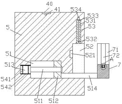
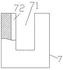
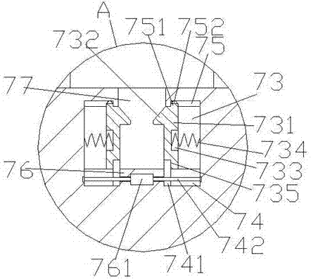
[0027] Such as Figure 1-Figure 8 As shown, a building construction facility of the present invention includes a connecting radio 5 and a connecting pin 6. The front and rear ends of the connecting radio 5 are correspondingly provided with a convex plate 40, and a light bulb 41 is installed at the lower end of the convex plate 40. 41 is used to facilitate the use of the connected radio station 5 at night, the right side of the connected radio station 5 is provided with an embedding groove 52, and the first movable warehouse 53 is provided in the connected radio station 5 at the top of the embedding groove 52, The connecting station 5 on the left side of the embedding groove 52 is provided with a second movable bin 51, and a connecting groove 521 is provided on the inner end of the left side of the embedding groove 52, and the second movable bin 51 is provided with There is a first stud 511 extending left and right. The left end of the first stud 511 is connected to the first el...


PUM


Abstract

The invention discloses building construction facility, comprising an electric connection table and an electric connection pin. Convex plates are correspondingly arranged on front and rear end faces of the electric connection table. Bulbs are mounted at the lower ends of the convex plates. A tight embedding slot is arranged in the right end face of the electric connection table. A first moving cabin is arranged in the electric connection table on the top of the tight embedding slot. A second moving cabin is arranged in the electric connection table at the left side of the tight embedding slot. An electric connection slot is arranged at the left inner end of the tight embedding slot. A first stud is arranged in the second moving cabin in a left and right expansion mode. The left end of the first stud is connected with a first electric drilling machine. A moving block is in thread matching connection with the first stud. A combination rod is arranged at the bottom of the right side of the moving block in a right expansion mode. The right expansion section of the combination rod resists against the tight embedding slot. A clamping device is arranged at the right end of the combination rod. The building construction facility is simple in structure, convenient for operation and high in safety. The electric connection pin can be automatically locked and positioned. The insertion work of the electric connection pin can be automatically controlled.

Description

Technical field [0001] The invention relates to the technical field of building construction and a building construction facility. Background technique [0002] In the process of building construction, most of the construction equipment needs electricity when in use. When electricity is used, the plug of the equipment is often directly inserted into the socket, so that the electrical plug is easy to loose in the socket, which will cause poor contact. There is a large current flowing through the socket, which is easily damaged by using an electric plug. Although there are plug sockets with mechanical locking devices on the market, there are still many shortcomings. For example, it cannot prevent manual unplugging, and the plug locking function is not good, that is, the plug may still fall out when the device is in use, which causes a greater safety hazard. , The equipment cannot be used normally. In addition, the existing equipment is manually plugged in when using electricity, a...

Claims


Application Information

Patent Timeline
IPC IPC(8): H01R13/627H01R13/629H01R13/44
CPCH01R13/6273H01R13/44H01R13/62933
Inventor 范全有
Owner SHISHI CHUANLANG MACHINERY DESIGN CO LTD
Learn More