Rotor conveying channel with shelling device

A conveying channel and rotor technology, applied in the manufacture of stator/rotor body, chute, transportation and packaging, etc., can solve the problems of scalding, many scrapped rotors, deformation and damage of the aluminum end of the rotor, etc.

Inactive Publication Date: 2017-10-03
DONGGUAN LIANZHOU INTPROP OPERATION MANAGEMENT CO LTD
View PDF0 Cites 0 Cited by
  • Summary
  • Abstract
  • Description
  • Claims
  • Application Information

AI Technical Summary

Problems solved by technology

The current process of shelling the rotor is generally to manually use pliers to clamp the rotor, which is prone to burn accidents during the process of shelling, and there is also a sit

Method used


Image

  • Rotor conveying channel with shelling device
  • Rotor conveying channel with shelling device
  • Rotor conveying channel with shelling device

Examples


Embodiment Construction

[0021] The specific implementation manners of the present invention will be further described in detail below in conjunction with the accompanying drawings and embodiments. The following examples are used to illustrate the present invention, but are not intended to limit the scope of the present invention.

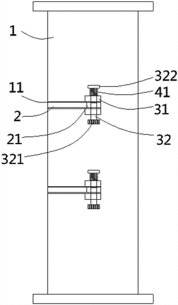
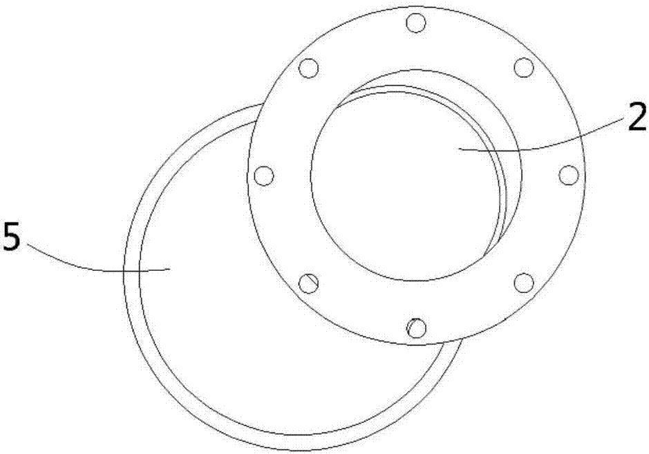
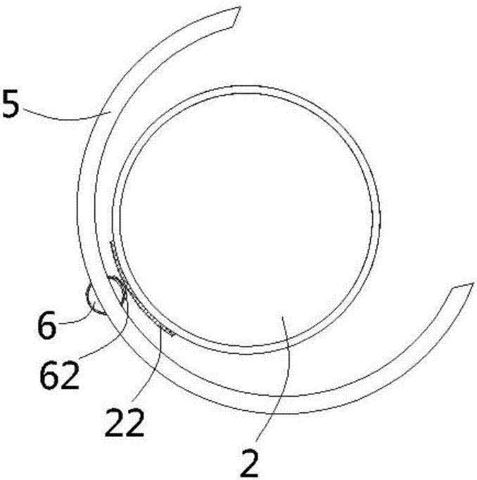
[0022] see figure 1 , a rotor conveying channel with a shelling device according to the present invention, comprising a vertical channel 1, the outer wall of the vertical channel 1 is formed with two arc-shaped slots 11 running through the inner wall of the vertical channel up and down, A spiral high-frequency tube (not shown) is inserted on the outer wall of the vertical channel 1 between the arc-shaped slots 11, and a circular tube that matches the arc-shaped slot 11 is inserted into the vertical channel 1. The baffle plate 2, the side wall of the baffle plate 2 is formed with a lug 21 passing through the arc-shaped slot 11, and the upper and lower sides of the lug 21 a...


PUM


Abstract

The invention discloses a rotor conveying channel with a shelling device, comprising a vertical channel, two arc-shaped grooves penetrating the inner wall of the vertical channel are formed on the outer wall of the vertical channel up and down, and the vertical channel is inserted A circular baffle matching the arc-shaped slot is connected, and the side wall of the baffle is formed with lugs passing through the arc-shaped slot. A first return torsion spring is set; an arc-shaped protective sleeve is fixed on the outer wall of the vertical channel around the arc-shaped slot, and an insertion hole penetrating through the outer wall of the protective sleeve is formed on the outer end side wall of the protective sleeve. An indicating ball is inserted into the insertion hole, and a fulcrum is formed on the inner wall of the insertion hole, the middle part of the indicating ball is inserted on the fulcrum, and a second reset torsion spring is inserted on the fulcrum, The first indicating color and the second indicating color are coated on the indicating ball. The invention not only facilitates the shelling treatment of the rotor, but also prevents personnel from being injured.

Description

Technical field: [0001] The invention relates to the technical field of motor rotors, in particular to a rotor conveying channel with a shelling device. Background technique: [0002] The stator and rotor are the important components of the motor. After the die-casting is completed, the rotor needs to be shelled to remove the aluminum on the rotor punching sheet, and at the same time prevent the aluminum and the punching sheet from being bonded together in the slot holes of the rotor punching sheet. The current process of shelling the rotor is generally to manually use pliers to clamp the rotor, which is prone to burn accidents during the process of shelling, and there is also a situation where the aluminum end of the rotor is deformed and damaged, which is not only poor in safety, but also occurs There are many scrapped rotors and it is necessary to improve them. [0003] In view of the above-mentioned defects, the designers are actively researching and innovating in orde...

Claims


Application Information

Patent Timeline
IPC IPC(8): H02K15/02B65G11/02B65G11/20
CPCH02K15/02B65G11/023B65G11/203
Inventor 徐亚维
Owner DONGGUAN LIANZHOU INTPROP OPERATION MANAGEMENT CO LTD
Why Eureka
Try Eureka