Positioning clamping device for machining of complex inner shape of thin-wall cylindrical workpiece

A thin-walled cylinder, positioning and clamping technology, used in positioning devices, metal processing equipment, metal processing machinery parts, etc. Convenience, ensure the shape and position tolerance, improve the effect of rigidity

Inactive Publication Date: 2017-10-10
江南工业集团有限公司
View PDF6 Cites 11 Cited by
  • Summary
  • Abstract
  • Description
  • Claims
  • Application Information

AI Technical Summary

Problems solved by technology

[0002] In the prior art, when processing the inner shape of thin-walled cylindrical parts based on the outer circle, the positioning method generally adopts the positioning inner hole surface matched with one end of the outer circle for positioning, and the positioning size of the positioning device is generally a rigid size, because There is a coaxiality error between the outer circle of the part and the positioning inner hole, and the rigidity of the part itself is poor, so that vibration occurs when the complex inner shape of the middle part of the part

Method used


Image

  • Positioning clamping device for machining of complex inner shape of thin-wall cylindrical workpiece
  • Positioning clamping device for machining of complex inner shape of thin-wall cylindrical workpiece
  • Positioning clamping device for machining of complex inner shape of thin-wall cylindrical workpiece

Examples


Embodiment Construction

[0032] The present invention will be further described below in conjunction with the accompanying drawings.

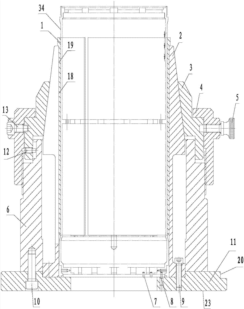
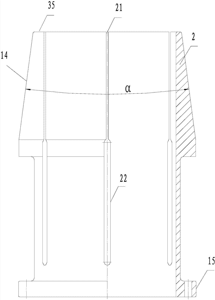
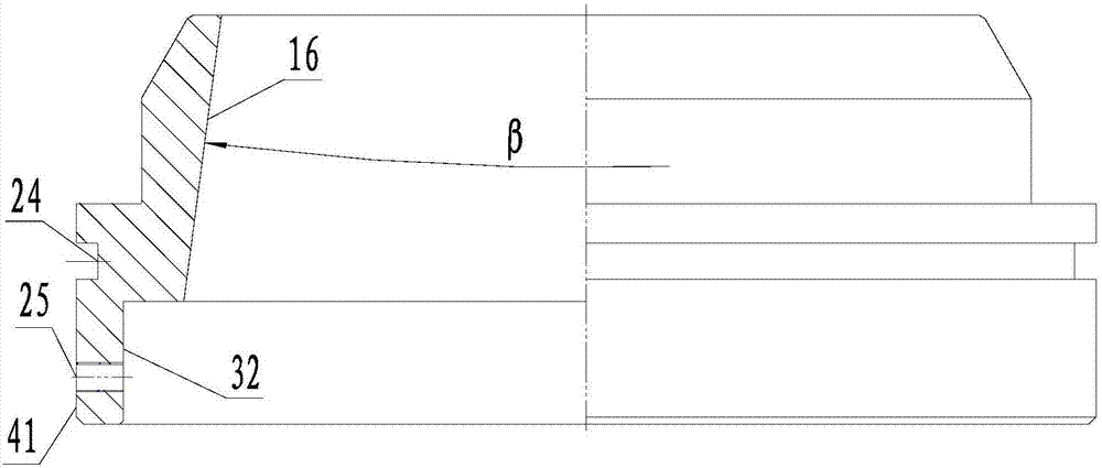
[0033] Such as Figures 1 to 6 As shown, the present invention includes a base 11 and a clip spring 2. The base 11 includes a base plate and a support 6 fixedly mounted on the base plate by screws 10. A calibration reference step 20 is provided on the side of the base plate as a calibration reference. The support 6 is cylindrical, and the top of the support 6 is provided with a taper sleeve 3 , and the upper part of the inner hole of the taper sleeve 3 is a second tapered surface 16 . The top of the support 6 is provided with a vertical guide groove 26, and the taper sleeve 3 is provided with a screw 12 corresponding to the guide groove, and the end of the screw 12 is placed in the guide groove, which can prevent the taper sleeve 3 from rotating and compressing the threaded sleeve 4. turn. The outer wall of the taper sleeve 3 is provided with an annular groove 24, an...


PUM


Abstract

The invention discloses a positioning clamping device for machining of a complex inner shape of a thin-wall cylindrical workpiece. The positioning clamping device comprises a base, a clip spring, a taper sleeve and a pressing threaded sleeve. The base is of a cylindrical structure, the taper sleeve is arranged at the upper end of the base, and the upper portion of an inner hole of the taper sleeve is provided with a second conical surface; the taper sleeve is connected with the pressing threaded sleeve which is in threaded connection with the side wall of the base, the clip spring is installed in an inner hole of the base, and the upper portion of the clip spring is provided with a first conical surface matched with the conical shape of the inner hole of the taper sleeve and provided with a groove joint which is axially formed; and the first conical surface is arranged in the second conical surface, and the lower portion of the clip spring is provided with a cylindrical surface which is matched with a positioning hole of the bottom of the base. According to the positioning clamping device, the structure is simple, operation is convenient, the taper sleeve is matched with the conical surface on the upper portion of the clip spring in the base, the taper sleeve is controlled by the pressing threaded sleeve to downwards move to achieve clamping of a clip spring on the thin-wall cylindrical type part, the stiffness of the part is improved, the shape and position tolerance of the part is ensured, the problem of vibration during thin-wall part machining is solved, and the machining efficiency and machining quality of the part are greatly improved.

Description

technical field [0001] The invention belongs to the technical field of fixtures for thin-walled cylindrical workpieces, in particular to a positioning and clamping device for complex inner shape processing of thin-walled cylindrical workpieces. Background technique [0002] In the prior art, when processing the inner shape of thin-walled cylindrical parts based on the outer circle, the positioning method generally adopts the positioning inner hole surface matched with one end of the outer circle for positioning, and the positioning size of the positioning device is generally a rigid size, because There is a coaxiality error between the outer circle of the part and the positioning inner hole, and the rigidity of the part itself is poor, so that vibration occurs when the complex inner shape of the middle part of the part is processed, the deformation of the part is enlarged again, the shape and position tolerance is out of tolerance, and the part assembly After going up, the f...

Claims


Application Information

Patent Timeline
IPC IPC(8): B23Q3/06
CPCB23Q3/065
Inventor 胡艳平刘国栋胡力徐心乐何少华刘虹伍浩
Owner 江南工业集团有限公司
Why Eureka
Try Eureka