A kind of driving device of printing head and thermal printer thereof

A driving device and print head technology, applied in printing and other directions, can solve problems such as inability to adjust, difficulty in taking out the carbon ribbon, and inability to reset

Active Publication Date: 2019-09-27
XIAMEN HANIN ELECTRONICS TECH CO LTD
View PDF8 Cites 0 Cited by
  • Summary
  • Abstract
  • Description
  • Claims
  • Application Information

AI Technical Summary

Problems solved by technology

[0003] The present invention provides a drive device for a printing head, aiming at improving the problem that the existing two-stage pressing motor of the printing head cannot be reset in the event of power failure and the problem that the printing pressure cannot be adjusted
[0004] The present invention provides a thermal printer, aiming at improving the problems that existing thermal printers cannot be reset in the event of power failure and the carbon ribbon is difficult to take out when they are applied in factories, thereby affecting production.

Method used


Image

  • A kind of driving device of printing head and thermal printer thereof
  • A kind of driving device of printing head and thermal printer thereof
  • A kind of driving device of printing head and thermal printer thereof

Examples


Embodiment 1

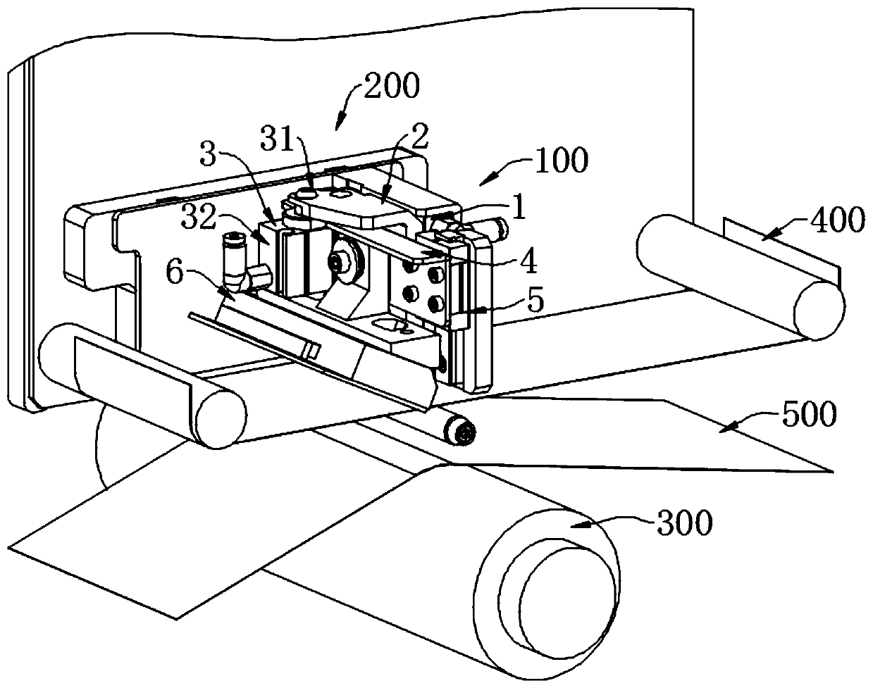
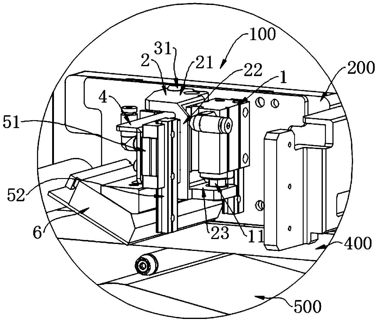
[0034] see Figure 1 to Figure 5 As shown, the driving device 100 includes a first driving member 1, a connecting bracket 2 and a second driving member 3, the first driving member 1 is arranged on the printer base 200, and the first driving member 1 has a first output shaft 11. The connecting bracket 2 is drivingly connected with the first output shaft 11 and moves back and forth relative to the position to be printed. The second drive member 3 has a second output shaft 31 and a first cylinder body 32, the second output shaft 31 is fixedly connected to the connecting bracket 2, and the second output shaft 31 expands and contracts so that the first cylinder The body 32 reciprocates between the position to be printed and the printing position; the print head 6 has a motion state of moving with the first cylinder body 32 .

[0035]The present invention connects the two driving parts to the connecting bracket 2, the print head 6 is connected to the second driving part 3, and the...

Embodiment 2

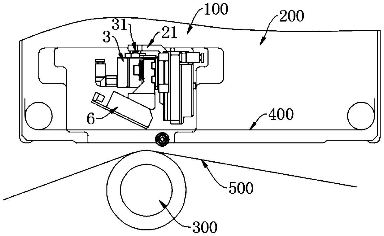
[0042] see Figure 1 to Figure 5 As shown, a thermal printer uses the driving device 100 in Embodiment 1, the printer also includes a printer base 200, a print head 6 and a rubber roller 300, and the driving device 100 is arranged on the printer base 200, The recording medium 500 passes between the printing head 6 and the rubber roller 300 , the printing head 6 is arranged on the driving device 100 , and the printing head 6 presses the carbon ribbon 400 against the recording medium 500 .

[0043] The printing head 6 moves to the position to be printed by the first driving member 1, and moves to the printing position by the second driving member 3, the rubber roller 300 is perpendicular to the moving direction of the printing head 6, and the The print head 6 is in line contact with the rubber roller 300 at the front of the rubber roller 300 . That is, the print head 6 is in contact with the rubber roller 300 on the busbar at the top of the rubber roller 300 to avoid the pressu...


PUM


Abstract

The invention provides a driving device for a printing head. The driving device comprises a first driving piece, a connecting support and a second driving piece, wherein the first driving piece is arranged on a printer base, and provided with a first output shaft; the connecting support is connected with the first output shaft in a driven mode, and can conduct reciprocating motion relative to a to-be-printed position; the second driving piece is provided with a second output shaft and a second cylinder body, the second output shaft is fixedly connected with the connecting support, and the second output shaft stretches out and draws back to enable the second cylinder body to conduct reciprocating motion between the to-be-printed position and a printing position; and the printing head has a motion state that the printing head can move along the second cylinder body. According to the driving device for the printing head and a thermal printer, the driving piece drives first stage press of the printing head to the to-be-printed position, and the second driving piece drives second stage press of the printing head to the printing position, so that the two-stage press of the printing head are driven through the two driving pieces, and the printing head can accurately stay at three different positions of the highest position, the to-be-printed position and the printing position.

Description

technical field [0001] The invention relates to the field of printers, in particular to a drive device for a print head and a thermal printer thereof. Background technique [0002] At present, the thermal transfer technology uses a special carbon ribbon to transfer the toner coating on the carbon ribbon to paper or other types of materials by using the print head after heating. Choose according to your needs to produce strong adhesion, coupled with the choice of printing media, can ensure that the printed handwriting will not be affected by the outside world. For thermal transfer coding equipment, at different times, the print head needs to stay at three positions with different heights and directions, namely the highest position when the ribbon is installed, the waiting position after the power-on self-test is completed, and the printing position during printing. When the printer is turned off, the print head is at the highest position, so that the ribbon can pass under th...

Claims


Application Information

Patent Timeline
Patent Type & Authority Patents(China)
IPC IPC(8): B41J2/32B41J23/00
Inventor 苏建洲
Owner XIAMEN HANIN ELECTRONICS TECH CO LTD
Why Eureka
Try Eureka