Supercharge Your Innovation With Domain-Expert AI Agents!

A binding device for a brake clutch plate

A clutch, strapping technology, applied in the direction of strapping materials, parts of strapping machinery, etc., can solve the problems of low safety, slow strapping speed, and time-consuming

Active Publication Date: 2019-05-17
江苏铭源物流有限公司
View PDF7 Cites 0 Cited by
  • Summary
  • Abstract
  • Description
  • Claims
  • Application Information

AI Technical Summary

Problems solved by technology

[0006] In order to overcome the shortcomings of the present invention, which generally bind the brake clutch plate models manually, it takes a lot of time and energy, the binding speed is slow, and the safety is low, the technical problem to be solved by the present invention is to provide a A binding device for brake and clutch discs that saves time and effort, improves the binding speed, and has high safety

Method used


Image

  • A binding device for a brake clutch plate
  • A binding device for a brake clutch plate
  • A binding device for a brake clutch plate

Examples


Embodiment 1

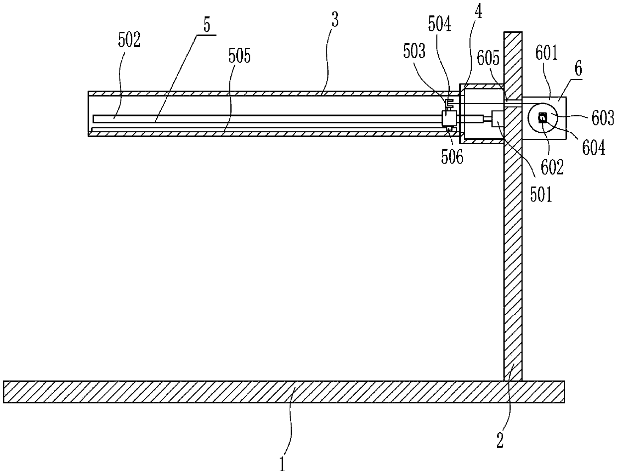
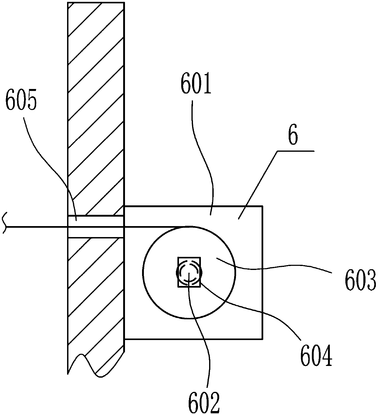
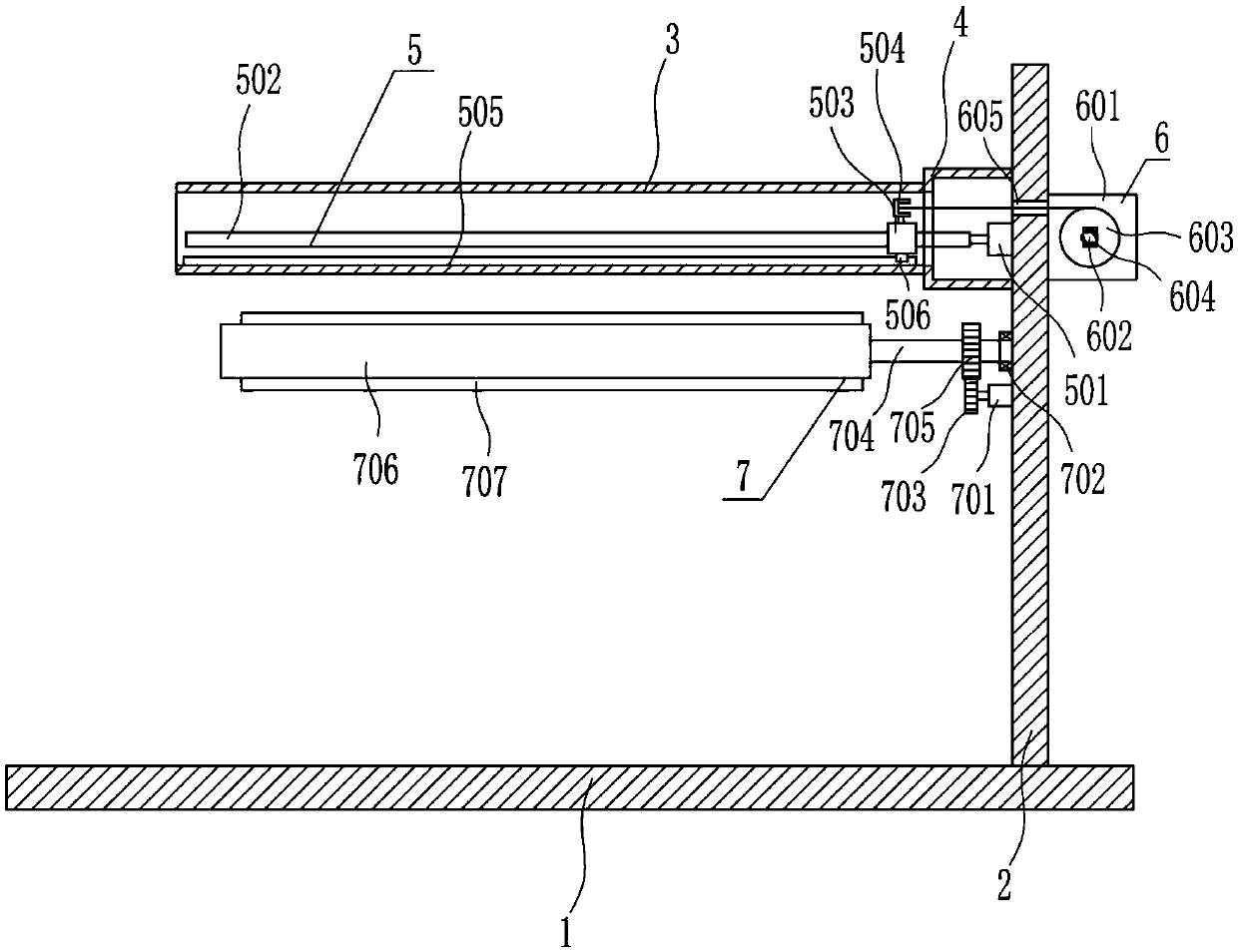
[0037] A binding device for a brake clutch plate, such as Figure 1-6 As shown, it includes a base plate 1, a support plate 2, a box body 3, an n-shaped frame 4, a left and right moving device 5 and a strap fixing device 6. The support plate 2 is welded on the right side of the top of the base plate 1, and the upper part of the left side of the support plate 2 is The n-shaped frame 4 is welded, and the left side of the n-shaped frame 4 has an opening. The left side of the n-shaped frame 4 is welded with a box body 3. As for the device 5, a strap fixing device 6 is provided on the upper right side of the support plate 2.

Embodiment 2

[0039] A binding device for a brake clutch plate, such as Figure 1-6 As shown, it includes a base plate 1, a support plate 2, a box body 3, an n-shaped frame 4, a left and right moving device 5 and a strap fixing device 6. The support plate 2 is welded on the right side of the top of the base plate 1, and the upper part of the left side of the support plate 2 is The n-shaped frame 4 is welded, and the left side of the n-shaped frame 4 has an opening. The left side of the n-shaped frame 4 is welded with a box body 3. As for the device 5, a strap fixing device 6 is provided on the upper right side of the support plate 2.

[0040] The left and right moving device 5 includes a first motor 501, a screw rod 502, a nut 503, a thumb cylinder 504, a first slide rail 505 and a first slide block 506, and the first motor 501 is connected with the top of the left side of the support plate 2 by bolts. A motor 501 is located in the n-type frame 4, the output shaft of the first motor 501 is...

Embodiment 3

[0042] A binding device for a brake clutch plate, such as Figure 1-6 As shown, it includes a base plate 1, a support plate 2, a box body 3, an n-shaped frame 4, a left and right moving device 5 and a strap fixing device 6. The support plate 2 is welded on the right side of the top of the base plate 1, and the upper part of the left side of the support plate 2 is The n-shaped frame 4 is welded, and the left side of the n-shaped frame 4 has an opening. The left side of the n-shaped frame 4 is welded with a box body 3. As for the device 5, a strap fixing device 6 is provided on the upper right side of the support plate 2.

[0043] The left and right moving device 5 includes a first motor 501, a screw rod 502, a nut 503, a thumb cylinder 504, a first slide rail 505 and a first slide block 506, and the first motor 501 is connected with the top of the left side of the support plate 2 by bolts. A motor 501 is located in the n-type frame 4, the output shaft of the first motor 501 is...


PUM


Abstract

The invention relates to a binding device for a brake clutch disc. According to the technical aims, the binding device for the brake clutch disc saves time and labor, improves the binding speed and is high in safety. In order to achieve the above technical aims, the binding device for the brake clutch disc comprises a base plate and the like; a supporting plate is welded to the right side of the top of the base plate, an n-shaped support is welded to the upper portion of the left side face of the supporting plate, an opening is formed in the left side of the n-shaped support, a box is welded to the left side of the n-shaped support, and the left and right sides of the box are arranged in an opening manner; and a left-and-right movement device is arranged in the box, and a binding belt fixing device is arranged at the upper portion of the right side face of the supporting plate. According to the binding device, a binding belt penetrates the brake clutch disc through the left-and-right movement device, then the brake clutch disc is manually bound, force borne by the box is reduced through a supporting device, and the service life of the box can be prolonged.

Description

technical field [0001] The invention relates to a binding device for brake clutch plates, in particular to a binding device for brake clutch plates. Background technique [0002] The clutch plate is a vulnerable part in the driving system of a motor vehicle. When using it, special attention should be paid to not keeping your feet on the clutch pedal when the engine is running. [0003] Braking, also known as braking, refers to the action of stopping or reducing the speed of running locomotives, vehicles and other means of transportation or machinery. The general principle of braking is to fix a wheel or disc on the high-speed shaft of the machine, install a corresponding brake shoe, belt or disc on the machine base, and make it generate braking torque under the action of external force. The brake device is also a mechanical brake device that can slow down the speed of the vehicle, also known as a reducer. To put it simply: the brake pedal of the car is under the steering w...

Claims


Application Information

Patent Timeline
Patent Type & Authority Patents(China)
IPC IPC(8): B65B13/02B65B13/18
CPCB65B13/02B65B13/18
Inventor 华鹏
Owner 江苏铭源物流有限公司
Features
  • R&D
  • Intellectual Property
  • Life Sciences
  • Materials
  • Tech Scout
  • Unparalleled Data Quality
  • Higher Quality Content
  • 60% Fewer Hallucinations
Learn More