
Array substrate and manufacturing method thereof

A manufacturing method and array substrate technology, applied in semiconductor/solid-state device manufacturing, semiconductor devices, electrical components, etc., can solve problems such as electrostatic discharge damage, process abnormalities, and impact on product quality, so as to prevent electrostatic discharge and improve quality. Effect

Active Publication Date: 2020-01-17
WUHAN CHINA STAR OPTOELECTRONICS TECH CO LTD
View PDF3 Cites 0 Cited by
  • Summary
  • Abstract
  • Description
  • Claims
  • Application Information

AI Technical Summary

Problems solved by technology

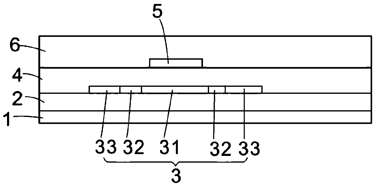
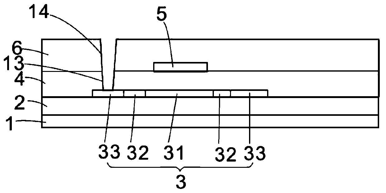
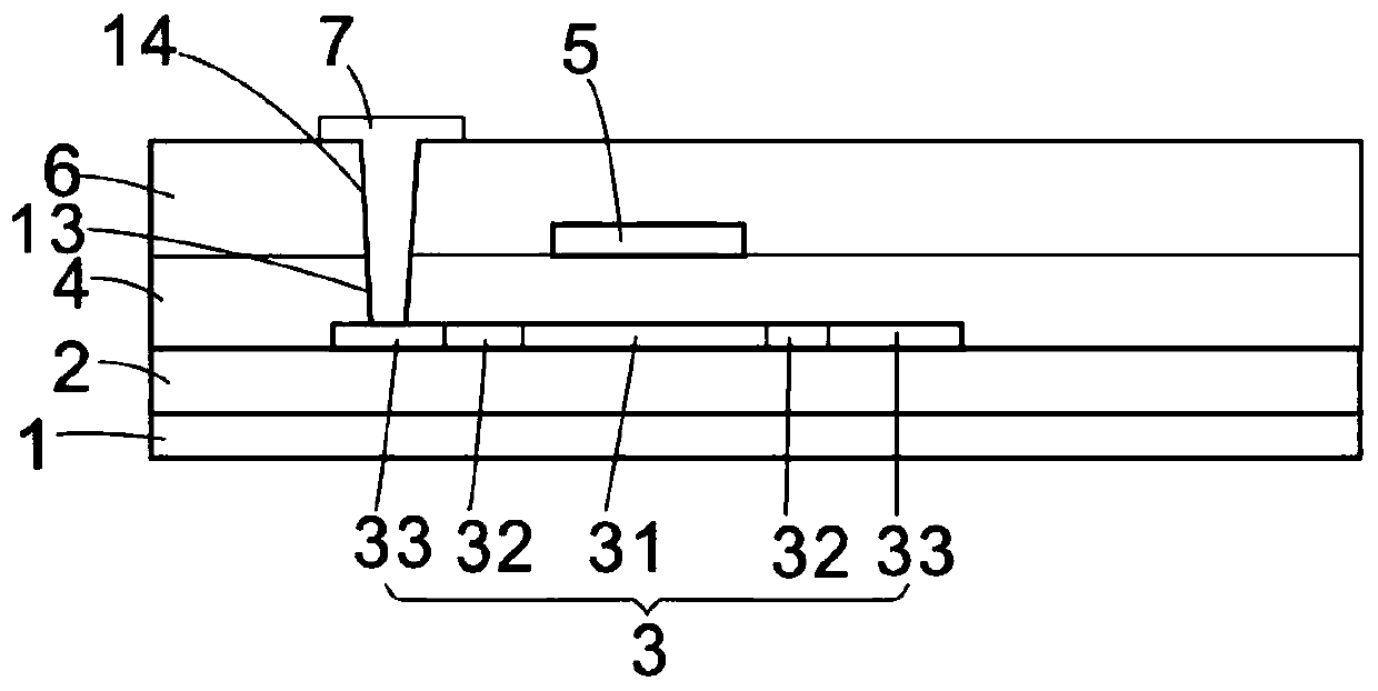
[0002] In the manufacturing process of low-temperature polysilicon liquid crystal display panel (LTPS TFT (thin film transistor) LCD (liquid crystal display)) on the traditional thin film transistor array substrate, firstly, a buffer layer, an active layer, and a gate insulating layer are sequentially fabricated on the substrate. , gate, and then make an interlayer insulating layer and etch the via holes to the source and drain terminals of the active layer. The via holes will expose part of the active layer, and then make the source\drain, make a flat layer, a common electrode, The passivation layer and the pixel electrode, the pixel electrode is in contact with the drain; in the traditional process, the via hole for the pixel electrode to contact the active layer is formed from the interlayer insulating layer, etched in the interlayer insulating layer (ILD) The active layer (poly) used to contact the pixel electrode is exposed; in the subsequent process, such as source / drain (SD), flat layer (PLN), common electrode (Com ITO), passivation layer ( PV CVD), pixel electrode (Pixel ITO), will transfer the generated static electricity and easily to the active layer (polysilicon polySi), resulting in electrostatic discharge (ESD) of the active layer located at the interlayer insulating layer via hole and gate , Electro-Staticdischarge) injury, resulting in process abnormalities, affecting product quality

Method used


Image

  • Array substrate and manufacturing method thereof
  • Array substrate and manufacturing method thereof
  • Array substrate and manufacturing method thereof

Examples


Embodiment Construction

[0034] The present invention will be further described in detail below with reference to the drawings and embodiments.

[0035] Such as Image 6 As shown, the array substrate of the present invention includes a substrate 1, a buffer layer 2, an active layer 3, a gate insulating layer 4, a gate 5, an interlayer insulating layer 6, and an interlayer insulating layer 6 sequentially disposed on the substrate 1. The first via 13 of the gate insulating layer 4 and the second via 14 of the gate insulating layer 4 are in contact with the source electrode 7, the flat layer 8, the common electrode 9, and the passivation layer 10 of the active layer 3; The source layer 3 is provided with a fourth via 91, the flat layer 8 is provided with a third via 81 at the fourth via 91, and a through fourth via 91 and a third via are provided on the passivation layer 10 81. The flat layer 8, the interlayer insulating layer 6, and the fifth via hole 11 of the gate insulating layer 4. A pixel electrode 1...


PUM


Abstract

The present disclosure provides an array substrate and a method of manufacturing the same. The array substrate includes a substrate, a buffer layer, an active layer, a gate insulating layer with a second via hole, a gate, an interlayer insulating layer with a first via hole, a source electrode contacting the active layer through the first and second via holes, a planarization layer with a third via hole, a common electrode with a fourth via hole and a passivation layer sequentially disposed on the substrate, and a pixel electrode disposed on the passivation layer contacts the active layer through a fifth via hole passing through the fourth and third via holes, the interlayer insulating layer, and the gate insulating layer. According to present disclosure, static electricity generated in manufacturing is effectively prevented from being transferred to the active layer to cause Electro-Static discharge, which further improves the product quality.

Description

Technical field [0001] The invention relates to a display panel technology, in particular to a low-temperature polysilicon array substrate and a manufacturing method thereof. Background technique [0002] In the traditional manufacturing process of LTPS TFT (thin film transistor) LCD (liquid crystal display), a buffer layer, an active layer, and a gate insulating layer are formed on the substrate in sequence. , The gate, and then make an interlayer insulating layer and etch to the via holes at the source and drain ends of the active layer. The via holes expose part of the active layer, and then make the source / drain, make the flat layer, the common electrode, The passivation layer and the pixel electrode, the pixel electrode and the drain are in contact; in the traditional process, the via hole for the pixel electrode and the active layer is formed from the interlayer insulating layer and etched in the interlayer insulating layer (ILD) The active layer (poly) used to contact the...

Claims


Application Information

Patent Timeline
Patent Type & Authority Patents(China)
IPC IPC(8): H01L27/12H01L21/77
CPCH01L27/1214H01L27/124H01L27/1259H01L29/66757H01L29/78621H01L29/78675H01L27/1251H01L27/1262
Inventor 张占东
Owner WUHAN CHINA STAR OPTOELECTRONICS TECH CO LTD
Learn More