A method and system for monitoring indoor distribution antenna feeders based on radio frequency identification

A technology of antenna feeder system and monitoring system, which is applied in near-field transmission system, read/write/query/recognition near-field transmission system, transmission system, etc. It is difficult to accurately estimate link loss and other issues, so as to improve system reliability, reduce implementation costs, and reduce construction costs

Active Publication Date: 2019-08-13
CHINA MOBILE COMM LTD RES INST +1
View PDF2 Cites 0 Cited by
  • Summary
  • Abstract
  • Description
  • Claims
  • Application Information

AI Technical Summary

Problems solved by technology

This solution has the following disadvantages: First, it is necessary to estimate the link loss to judge the working status of the antenna feeder system, but the link loss of each feeder path in the actual antenna feeder system is not the same, so it is difficult to accurately estimate the The link loss of the feeder channel leads to errors in the monitoring results
This solution has the following disadvantages: First, the signal source device can support the transmission of the base station signal required for communication and the monitoring signal required for monitoring, but the base station signal and the monitoring signal cannot be sent at the same time
This solution has the following disadvantages: First, the RFID tag does not add a radio frequency band-pass filter, which will cause the base station signal to interfere with the RFID signal and affect the normal operation of the RFID communication system
This solution has the following disadvantages: the RFID tag does not add a radio frequency band-pass filter, which will cause the base station signal to interfere with the RFID signal and affect the normal operation of the RFID communication system

Method used


Image

  • A method and system for monitoring indoor distribution antenna feeders based on radio frequency identification
  • A method and system for monitoring indoor distribution antenna feeders based on radio frequency identification
  • A method and system for monitoring indoor distribution antenna feeders based on radio frequency identification

Examples


Embodiment Construction

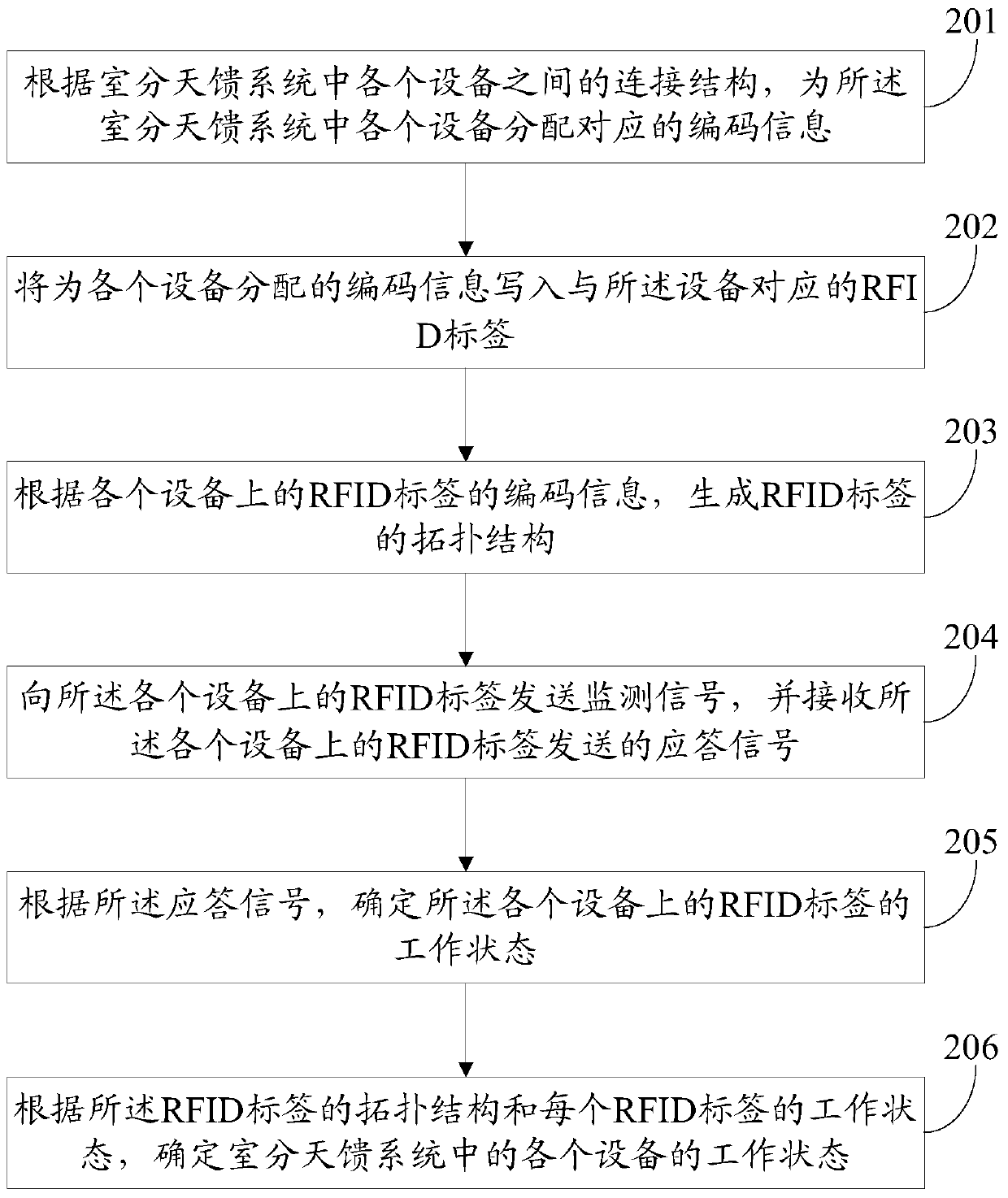
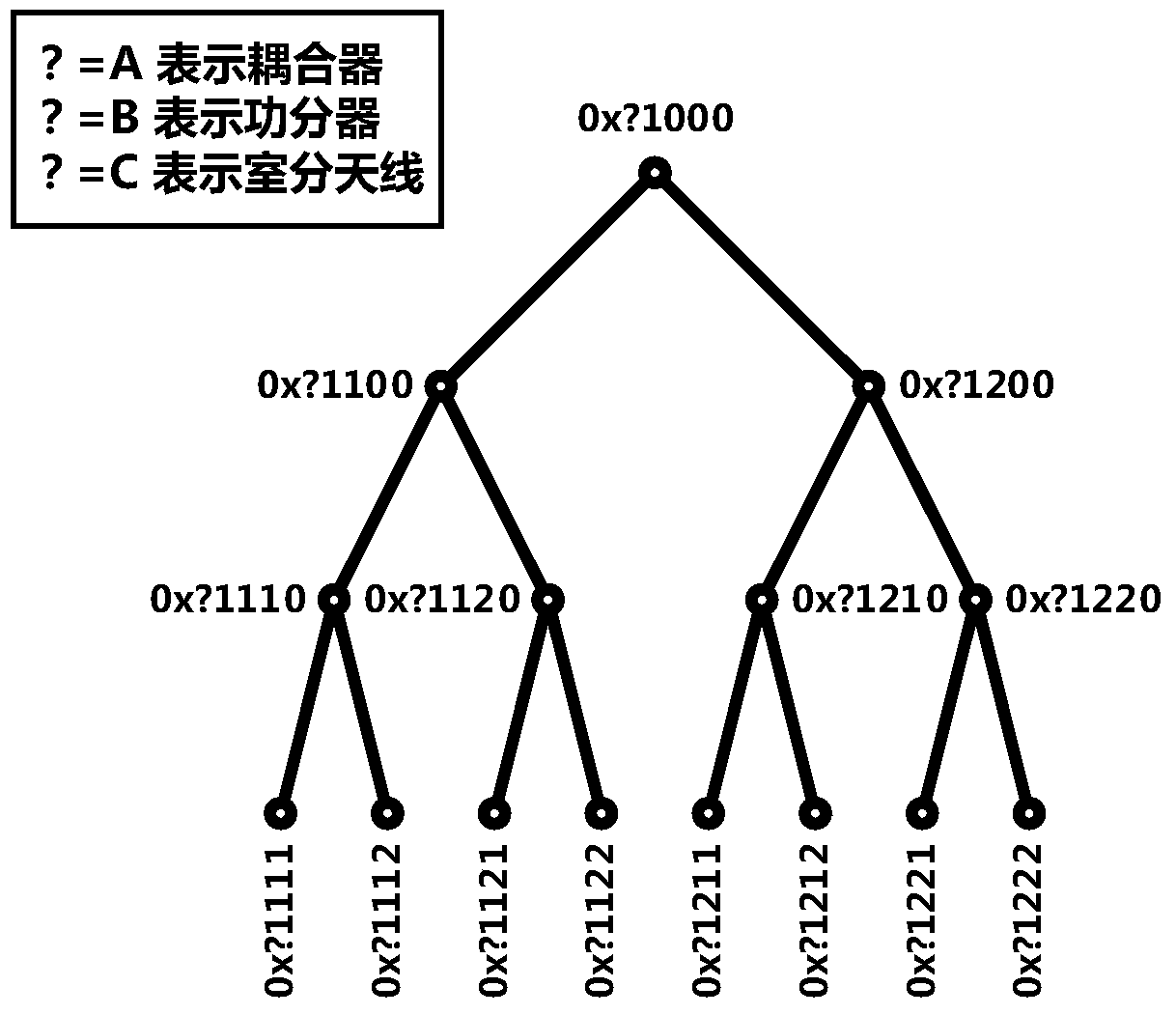
[0053] In order to understand the characteristics and technical content of the embodiments of the present invention in more detail, the implementation of the embodiments of the present invention will be described in detail below with reference to the accompanying drawings. The attached drawings are for reference and explanation purposes only, and are not used to limit the embodiments of the present invention.

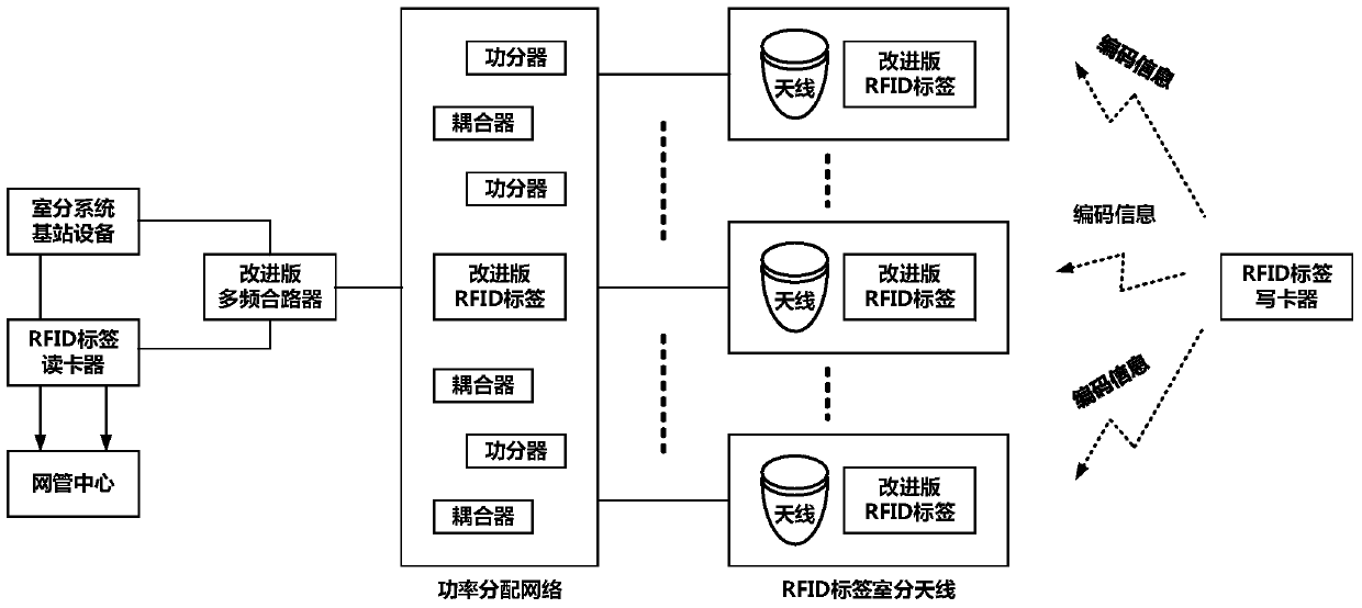
[0054] The embodiment of the present invention provides an RFID-based indoor distribution antenna feed monitoring system. The indoor distribution antenna feed monitoring system includes: base station, RFID tag reader, network management center, combiner, power distribution network, indoor distribution antenna, RFID Tag writer. In a specific embodiment, the base station is an indoor system base station equipment, the combiner is an improved version of a multi-frequency combiner, the indoor antenna is an RFID tag, and the RFID tag is an improved tag.

[0055] figure 2 It is a...


PUM


Abstract

The invention discloses an indoor distribution antenna feeder monitoring method and system based on RFID. The method comprises the following steps: setting RFID labels on devices in an indoor distribution antenna feeder system; allocating corresponding encoding information to the devices in the indoor distribution antenna feeder system according to connecting structures among the devices in the indoor distribution antenna feeder system; writing the encoding information allocated to the devices in the RFID labels corresponding to the devices; generating topological structures of the RFID labels according to the encoding information of the RFID labels on the devices; sending monitoring signals to the RFID labels on the devices, and receiving answer signals sent by the RFID labels on the devices; determining the working states of the RFID labels on the devices according to the answer signals; and determining the working states of the devices in the indoor distribution antenna feeder system according to the topological structures of the RFID labels and the working state of each RFID label.

Description

Technical field [0001] The present invention relates to wireless communication technology, and in particular to a method and system for monitoring a room divider antenna feeder based on wireless equipment identification (RFID, Radio Frequency Identification). Background technique [0002] As people’s demand for the mobile Internet is increasing, and mobile users’ demand for network quality and traffic continues to increase, many important indoor venues use indoor distributed antenna feeder systems to enhance coverage and capacity. In the indoor distribution system, the antenna feeder system is responsible for signal transmission and distribution. Once the antenna feeder system has problems, it will directly affect the signal coverage. However, the antenna feeder system is mostly built with passive components and does not have the function of autonomous monitoring and warning of working status. Therefore, how to monitor the operating status of the antenna feeder system has become...

Claims


Application Information

Patent Timeline
Patent Type & Authority Patents(China)
IPC IPC(8): H04W24/04H04B5/00
CPCH04B5/0062H04W24/04
Inventor 张欣旺曹景阳张敏王军
Owner CHINA MOBILE COMM LTD RES INST
Why Eureka
Try Eureka