Heat dissipation integrated cabinet for communication equipment

A technology for communication equipment and cabinets, which is applied in the construction of electrical equipment components, cooling/ventilation/heating transformation, electrical components, etc., which can solve the problems of damaging electrical components, affecting the normal needs of electrical components, and damage to electrical components in the control cabinet. Achieve the effect of preventing rainwater or snow from entering, heat dissipation and drying in a timely manner, and good sealing

Inactive Publication Date: 2017-10-10
合肥念萍电子商务有限公司
View PDF8 Cites 16 Cited by
  • Summary
  • Abstract
  • Description
  • Claims
  • Application Information

AI Technical Summary

Problems solved by technology

However, since these outdoor communication devices generate heat during work, and can only operate normally within a certain temperature range, it is necessary to set up a cooling device for these outdoor communication devices. Communication signal base stations generally need to install communication devices and control devices connected to communication devices. Cabinet, the electrical components in the control cabinet will generate heat when they work, and the high temperature will affect the normal needs of the electrical components, so the control cabinet generally has heat dissipation slots on the cabinet door, but because some control cabinets are installed in Outdoor, so that rainwater will enter the control cabinet from the heat dissipation slot on the cabinet door, which will cause damage to the electrical components in the control cabinet, or produce water vapor to damage the electrical components

Method used


Image

  • Heat dissipation integrated cabinet for communication equipment
  • Heat dissipation integrated cabinet for communication equipment
  • Heat dissipation integrated cabinet for communication equipment

Examples


Embodiment Construction

[0018] The following will clearly and completely describe the technical solutions in the embodiments of the present invention with reference to the accompanying drawings in the embodiments of the present invention. Obviously, the described embodiments are only some, not all, embodiments of the present invention. Based on the embodiments of the present invention, all other embodiments obtained by persons of ordinary skill in the art without making creative efforts belong to the protection scope of the present invention.

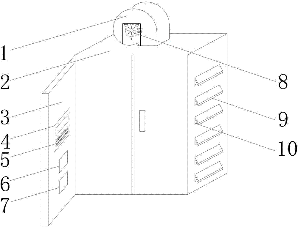
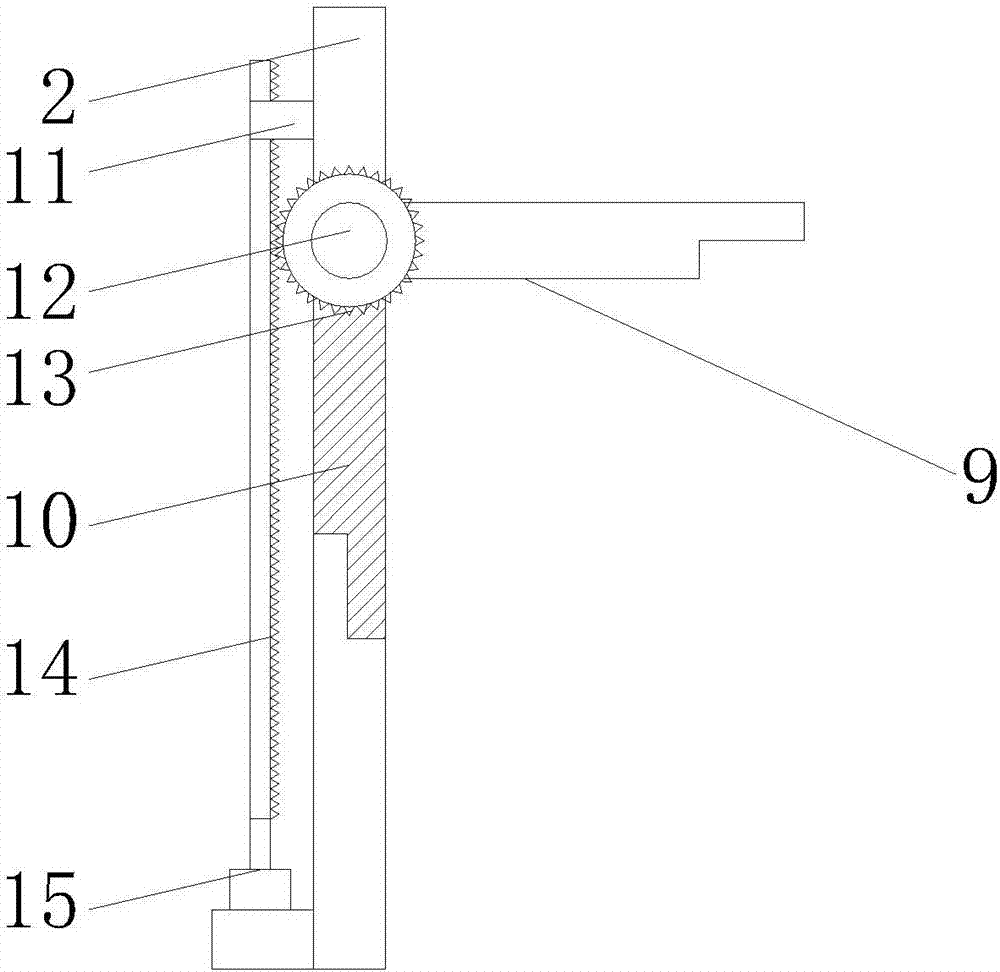
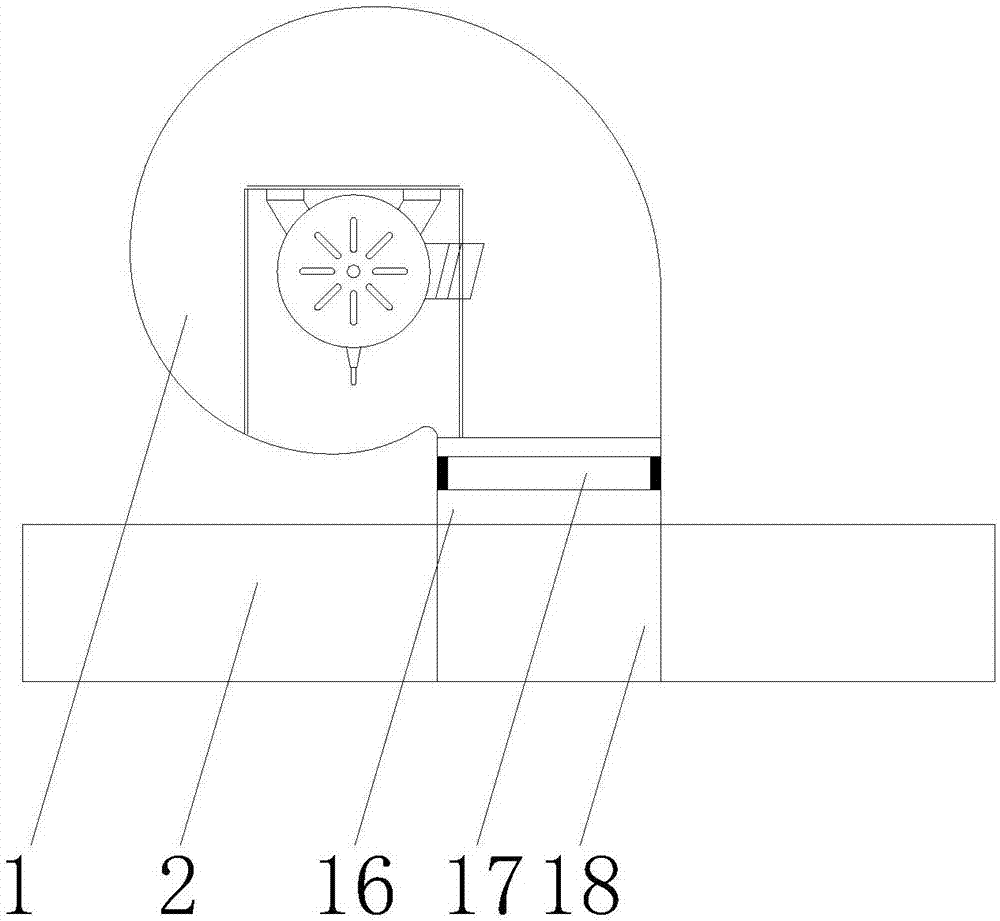
[0019] see Figure 1-3 , an embodiment provided by the present invention: a comprehensive heat dissipation cabinet for communication equipment, including a fan 1, a cabinet body 2, a controller 4, a ventilation cover 9 and an electric push rod 15, and the upper end of the cabinet body 2 is provided with an air inlet channel 18 , and the air inlet channel 18 is connected to the air outlet 16, and the other end of the air outlet 16 is connected to the fan 1, and...


PUM


Abstract

The invention discloses a heat dissipation integrated cabinet for communication equipment. The heat dissipation integrated cabinet comprises a draught fan, a cabinet body, a controller, ventilation covers and an electric push rod, wherein an air inlet passage is formed in an upper end of the cabinet body and is connected with an air outlet, the other end of the air outlet is connected with the draught fan, a heater is arranged in the air outlet, an air inlet is formed in one side of the draught fan, the controller is arranged on an inner wall of a cabinet door and is electrically connected with a control panel through a wire, a temperature sensor and a humidity sensor are arranged at a lower end of the controller, ventilation holes are formed in a side wall of the cabinet body, the ventilation covers are arranged at upper ends of the ventilation holes and are rotatably connected with the cabinet body by a rotation shaft, gears are fixedly arranged at two ends of the rotation shaft and are connected with a rack in the cabinet body, and the electric push rod is fixedly arranged at a lower end of the rack. The communication equipment can be cooled by the draught fan, heat dissipation is automatically controlled by the controller, and timely heat dissipation is achieved.

Description

technical field [0001] The invention relates to the technical field of heat dissipation of communication equipment, in particular to a comprehensive heat dissipation cabinet for communication equipment. Background technique [0002] At present, in the communication network, there are a large number of outdoor communication equipment placed outdoors, such as high-power cabinets of communication base stations. However, since these outdoor communication devices generate heat during work, and can only operate normally within a certain temperature range, it is necessary to set up a cooling device for these outdoor communication devices. Communication signal base stations generally need to install communication devices and control devices connected to communication devices. Cabinet, the electrical components in the control cabinet will generate heat when they work, and the high temperature will affect the normal needs of the electrical components, so the control cabinet generally ...

Claims


Application Information

Patent Timeline
Patent Type & Authority Applications(China)
IPC IPC(8): H05K7/20
CPCH05K7/20145
Inventor 袁先念
Owner 合肥念萍电子商务有限公司
Why Eureka
Try Eureka