
A sheet metal forming device and forming method capable of reducing the minimum bending radius of the sheet metal

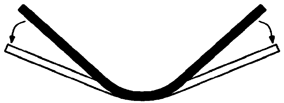
A bending radius, sheet metal technology, applied in the field of sheet metal forming devices, can solve the problems of increasing tensile stress value, prone to rupture, increasing tension and bending tooling, etc., to suppress sheet material springback, avoid excessive thickness reduction, Eliminate the effect of sheet springback

Active Publication Date: 2019-01-15
CENT SOUTH UNIV
View PDF5 Cites 0 Cited by
  • Summary
  • Abstract
  • Description
  • Claims
  • Application Information

AI Technical Summary

Problems solved by technology

But this requires the addition of complex stretch bending tools, and stretch bending is mainly for sheet metal forming with large fillet radius
For bending with a small fillet radius, the outer layer of the sheet itself is subjected to a large tensile stress. If the tensile stress is applied along the length of the sheet, the tensile stress value of the outer layer of the sheet bending angle will become larger and more likely to occur rupture

Method used


Image

  • A sheet metal forming device and forming method capable of reducing the minimum bending radius of the sheet metal
  • A sheet metal forming device and forming method capable of reducing the minimum bending radius of the sheet metal
  • A sheet metal forming device and forming method capable of reducing the minimum bending radius of the sheet metal

Examples


Embodiment

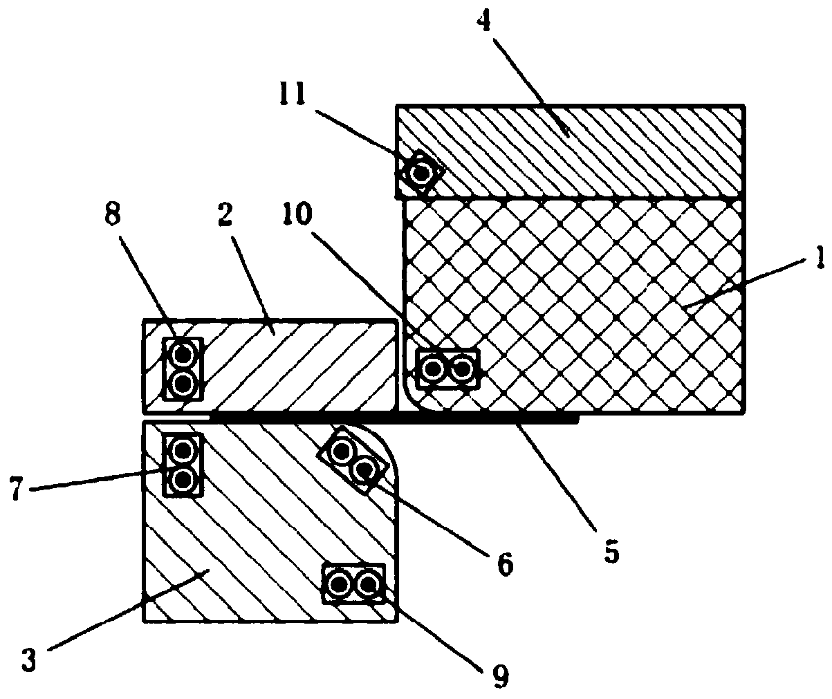
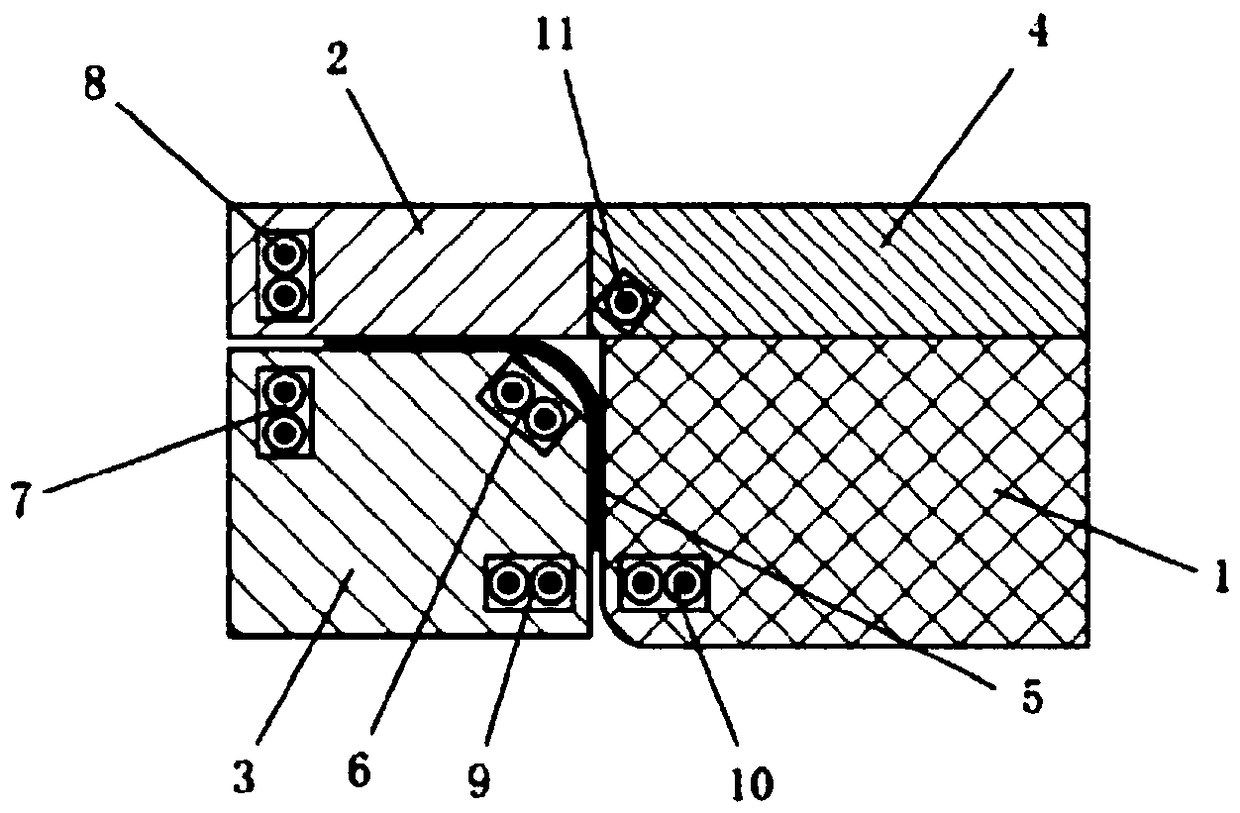
[0036] Such as Figure 2 to Figure 7As shown, a sheet metal forming device that can reduce the minimum bending radius of the sheet metal of the present invention includes a punch 1, a die 3, a blank holder 2, a press plate 4 and a power supply system (not shown in the figure). Wherein, the blank holder 2 is arranged above the die 3 and is used for clamping the blank 5 to be formed between the die 3 and the blank holder 2 . A bulging coil 6 is embedded in the rounded corner of the die 3 . The upper part of the die 3 is embedded with a first side pushing coil 7 on a side away from the fillet. A second side pushing coil 8 is embedded on the blank holder 2 corresponding to the first side pushing coil 7 . A third side push coil 9 is embedded below the fillet on the die 3 . A fourth side push coil 10 is embedded in the lower part of the punch 1 . A reverse bending coil 11 is embedded at the lower corner of the pressing plate 4 , and the reverse bending coil 11 can reversely defo...


PUM


Abstract

The invention discloses a plate forming device and forming method capable of reducing the minimum bending radius of plates. The device comprises a convex mould, a concave mould, a side pressing ring, a pressure plate and a power supply system, wherein the side pressing ring is arranged above the concave mould; an expanding coil is embedded into a circular bead of the concave mould; one side, away from the circular bead, of the upper part of the concave mould is embedded with a first side pushing coil; a second side pushing coil is arranged on a position, which corresponds to the first side pushing coil, of the side pressing ring; a third side pushing coil is embedded into a position, below the circular bead, of the concave mould; a fourth side pushing coil is embedded into the lower part of the convex mould; the lower corner of the pressure plate is embedded with an inflecting coil which prevents a bending angle of the plate from reverse deformation; and the power supply system supplies power to the expanding coil, the first side pushing coil, the second side pushing coil, the third side pushing coil, the fourth side pushing coil and the inflecting coil. The forming device can reduce the minimum bending radius value of the plate, prevents the outer layer of the plate from bending and cracking, and can inhibit the plate from rebounding.

Description

technical field [0001] The invention relates to the technical field of material plastic forming, in particular to a plate forming device and a forming method capable of reducing the minimum bending radius of the plate. Background technique [0002] Bending is one of the most common plastic deformation methods, which occurs in almost all sheet metal forming processes. When bending, the fibers on the side close to the center of curvature in the deformation zone, that is, the inner layer, are compressed tangentially, resulting in compression deformation; the fibers on the side away from the center of curvature, that is, the outside, are stretched, resulting in elongation deformation. As the relative bending radius R / t decreases, the degree of bending deformation gradually increases, and the maximum tensile deformation of the outer edge fibers also increases. When R / t is reduced to the extent that the tensile deformation of the fiber at the edge of the outer layer exceeds the a...

Claims


Application Information

Patent Timeline
Patent Type & Authority Patents(China)
IPC IPC(8): B21D5/04B21D26/14B21D37/10
CPCB21D5/04B21D26/14B21D37/10
Inventor 崔晓辉王青山喻海良
Owner CENT SOUTH UNIV
Learn More