A method for defogging uuv visible light images near the sea

A visible light and image technology, applied in the field of optical vision imaging

Active Publication Date: 2020-09-11
HARBIN ENG UNIV
View PDF9 Cites 0 Cited by
  • Summary
  • Abstract
  • Description
  • Claims
  • Application Information

AI Technical Summary

Problems solved by technology

However, median filtering is not a good edge-preserving filtering method

Method used


Image

  • A method for defogging uuv visible light images near the sea
  • A method for defogging uuv visible light images near the sea
  • A method for defogging uuv visible light images near the sea

Examples


Embodiment Construction

[0036] In order to make the object, technical solution and advantages of the present invention clearer, the present invention will be further described in detail below in conjunction with the accompanying drawings and specific embodiments.

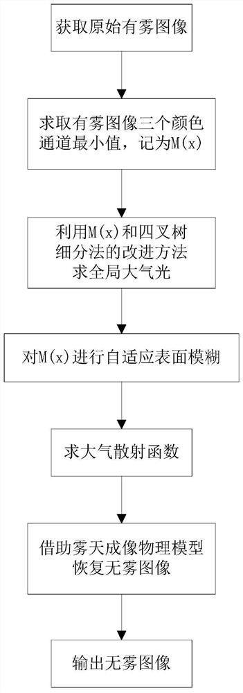
[0037] like figure 1 As shown, a UUV offshore visible light image defogging method includes the following steps:

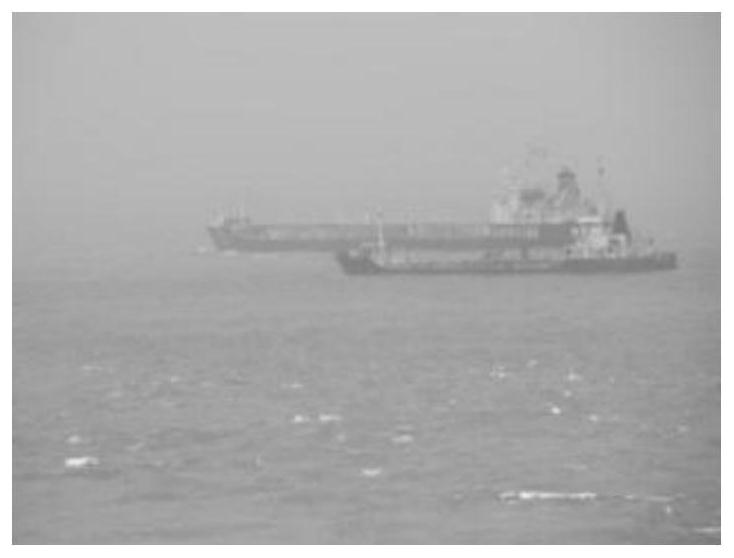
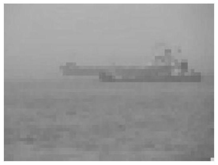
[0038] 1. Use VS2010 and OPENCV language programming to input and display the visible light reconnaissance image of the UUV offshore surface, denoted as I(x), and the visible light image is as follows figure 2 shown. Take the minimum value of the three color channels for I(x), record

[0039]

[0040] Image M(x) such as image 3 shown.

[0041] 2. Utilize the improved method of M(x) and quadtree subdivision method to obtain the steps of global atmospheric light comprising:

[0042] (1) Divide the picture into four rectangular areas.

[0043] (2) Calculate the average pixel value and variance of each region, and subtr...


PUM


Abstract

The invention provides a UUV near sea surface visible light image defogging method. According to the method, (1), an original foggy image is acquired, and the minimum value of three color channels is solved and is recorded as M(x); (2), an improved method of M(x) and a quadtree segmentation method is utilized to solve global atmosphere light; (3), adaptive surface fuzziness of the M(x) is carried out; (4), an atmosphere scattering function is solved; and (5), a fog imaging physical model is utilized to solve a no-fog image which is outputted. According to the method, adaptive surface fuzziness of the minimum value image of the three color channels is carried out, each pixel has a respective convolution matrix, edges of a target object can be excellently kept, subsequent target identification, positioning and tracking are facilitated, moreover, for solving a problem of a local dark phenomenon after filtering, the global atmosphere light is utilized to roughly divide the image into a dark area and a bright area, and different radiuses are utilized for fuzzy processing. The method is advantaged in that the relatively good defogging effect is realized, and a sky halation phenomenon can be overcome.

Description

technical field [0001] The invention relates to an optical vision imaging method, in particular to a method for defogging visible light images of a UUV offshore surface. Background technique [0002] China has a long coastline and complex weather conditions at sea. Ship collision accidents caused by sea fog are not uncommon. When light propagates in the atmospheric medium, it is refracted or reflected by suspended particles, which causes a large number of features in the video images taken by cameras installed on maritime buoys or UUVs to be covered up, the contrast is reduced, and the edge details are blurred, which is easy to cause misjudgment of image content. Thus, it will affect the subsequent target positioning, identification and tracking. Therefore, dehazing of optical vision images at sea is a practical and challenging problem. [0003] In the document "Single Image Haze Removal Using Dark Channel Prior" (Proceedings of IEEE CVPR. Miami, USA: IEEE Computer Society...

Claims


Application Information

Patent Timeline
Patent Type & Authority Patents(China)
IPC IPC(8): G06T5/00G06T7/11
CPCG06T5/003G06T7/11G06T2207/30181
Inventor 管凤旭周丽萍严浙平张宏瀚周佳加车浩刘怀东
Owner HARBIN ENG UNIV
Why Eureka
Try Eureka