Stacked-plate heat exchanger

A technology of heat exchangers and stacked plates, applied in the direction of heat exchanger types, indirect heat exchangers, fixed plate conduit assemblies, etc., can solve expensive and complicated problems, achieve good cooling, extend service life, and minimize pressure loss Effect

Inactive Publication Date: 2017-10-13
MAHLE INT GMBH
View PDF6 Cites 0 Cited by
  • Summary
  • Abstract
  • Description
  • Claims
  • Application Information

AI Technical Summary

Problems solved by technology

[0006] However, the stacked plate heat exchangers known from the prior art have the disadvantage that, even in terms of mass production, they can only be produced in a relatively complicated manner and are therefore expensive

Method used


Image

  • Stacked-plate heat exchanger
  • Stacked-plate heat exchanger

Examples


Embodiment Construction

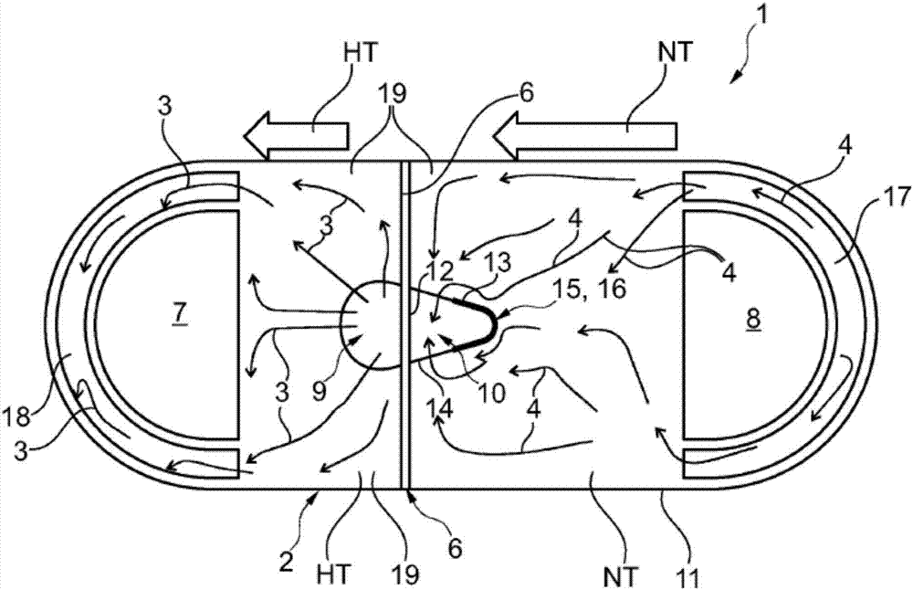
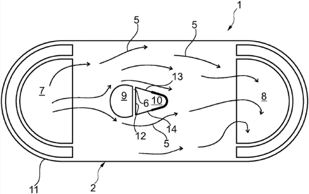
[0021] according to figure 1 , the stacked-plate heat exchanger 1 according to the invention, for example configured as a charge air cooler, comprises a high-temperature coolant circuit HT and a low-temperature coolant circuit NT. The respective coolant circuits HT and NT are formed by heat exchanger plates 2 stacked on top of each other through which two coolants 3 , 4 with different temperature levels flow in the high temperature coolant circuit HT and the low temperature coolant circuit NT. The medium 5 to be cooled (for example charge air) flows in a plane parallel to it (see figure 2 ). According to the invention, the heat exchanger plate 2 comprises a partition wall 6 which separates the high-temperature coolant circuit HT and the low-temperature coolant circuit NT from each other. This dividing wall 6 does not pass through the plane 5 of the medium, i.e. the charge air plane, so that charge air or medium 5 can flow from the medium inlet 7 over the entire length of th...


PUM


Abstract

The invention relates to a stacked-plate heat exchanger (1), in particular an intercooler, comprising a high-temperature coolant circuit (HT) and a low-temperature coolant circuit (NT) and comprising heat-exchanger plates (2) stacked one on the other, through which two coolants (3, 4) having a different temperature level in the high-temperature coolant circuit (HT) and in the low-temperature coolant circuit (NT) flow on one side and a medium (5) to be cooled, in particular charge air, flows on the other side. Said heat-exchanger plates (2) comprise a separating wall (6) for separating the high temperature coolant circuit (HT) and the low temperature coolant circuit (NT), such that the high temperature coolant circuit (HT) comprises a HT coolant inlet (9) which is central and adjacent to the separating wall (6), and the low temperature coolant circuit (NT) comprises a NT-coolant outlet (10) which is also central and adjacent to the separating wall (6).

Description

technical field [0001] The invention relates to a stacked plate heat exchanger according to the preamble of claim 1 , in particular a charge air cooler, having a high-temperature coolant circuit and a low-temperature coolant circuit. Background technique [0002] In modern motor vehicles, for example in the field of charge air cooling, continuously increasing cooling requirements can be observed, with the result that the demands on cooling and air conditioning systems are continuously increasing. Improved use of heat sources and heat sinks can lead to greater utilization but lower fuel consumption. Cooling systems currently available on the market for charge air cooling generally comprise stacked plate heat exchangers, which consist of a single stage. However, there is a limit to the efficiency that can be achieved with single-stage temperature regulation. In order to improve the efficiency of the cooling circuit, especially for cooling fluids such as for example coolant, ...

Claims


Application Information

Patent Timeline
IPC IPC(8): F28D9/00
CPCF28D9/0093F28D7/0066F28D7/0075F28D9/005
Inventor 马尔科·伦茨贝恩德·施默林格尔亨宁·施罗德福尔克尔·费尔特
Owner MAHLE INT GMBH
Why Eureka
Try Eureka