
Chopping board device

A cutting board and board surface technology, applied in the field of kitchen utensils, can solve the problems of cutting board pollution and user inconvenience, and achieve the effect of easy cleaning

Inactive Publication Date: 2017-10-17
宁波建辰新型材料有限公司
View PDF9 Cites 0 Cited by
  • Summary
  • Abstract
  • Description
  • Claims
  • Application Information

AI Technical Summary

Problems solved by technology

[0003] Existing chopping boards are usually plate-shaped made of plastic, bamboo and other materials, which makes one side of the chopping board must contact the counter when in use, which will cause pollution of the chopping board
In addition, when the cutting board is in use, the remaining cleaning water and the juice of the food itself will flow out and flow into the counter through the cutting board, which will bring a lot of inconvenience to the user

Method used


Image

  • Chopping board device
  • Chopping board device
  • Chopping board device

Examples


Embodiment 1

[0040] This embodiment provides a chopping board, and the chopping board is provided with a drain rack, so as to facilitate draining.

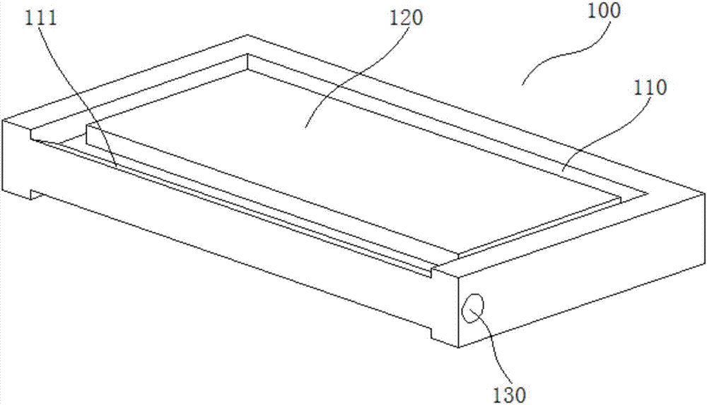
[0041]A chopping board in this embodiment includes a plate-shaped chopping board main body 100 , and a draining rack is provided on the chopping board main body 100 .

[0042] Such as figure 1 Shown is a schematic diagram of the cutting board main body 100 .

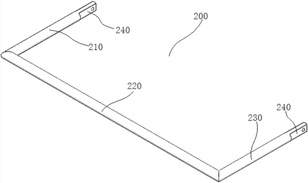
[0043] Such as figure 2 As shown, the drain rack includes a "U" shaped drain rack body 200 as a whole, and the drain rack body 200 includes a first strut 210 , a second strut 220 and a third strut 230 integrally connected in sequence.

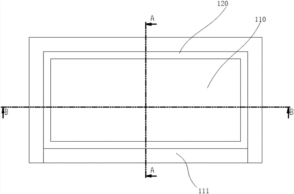
[0044] combine Figure 3-5 As shown, the two board surfaces of the chopping board main body 100 are provided with an annular sump 110, the middle part of the sump 110 is a vegetable cutting area 120, and the sump 110 is located at the other side opposite to the one side of the chopping board main body 100. The sidewall is inwardly recessed to form a ...

Embodiment 2

[0056] This embodiment provides a cutting board device, which is preferably convenient for users to use.

[0057] Such as Figure 10 , 13 As shown in and 14, an anvil device of the present embodiment includes an anvil bracket 1000, an anvil body 100 is provided at an anvil bracket 1000; an anvil bracket 1000 includes an anvil bracket main body 1010, an The anvil board placement groove 1011 of the main body 100; one side of the anvil board main body 100 is provided with a rotating shaft hole 130 along the length direction, and a rotating shaft 1012 is arranged in the rotating shaft hole 130, and both ends of the rotating shaft 1012 protrude from the rotating shaft hole 130; the anvil board placement groove 1011 corresponds to The side walls at both ends of the rotating shaft 1012 are provided with sliding grooves 1013, and the two ends and the middle of the lower side walls of the sliding groove 1013 are respectively provided with a first positioning groove 1013a, a second pos...


PUM


Abstract

The invention relates to the technical field of kitchen appliances, in particular to a chopping board device. The chopping board device comprises a chopping board support and a chopping board body. The chopping board support comprises a chopping board support body. A chopping board containing groove for containing the chopping board body is formed in the upper end face of the chopping board support body. A chopping board support supporting base is arranged below the chopping board support body and comprises four supporting legs. A stabilizing mechanism is arranged below any supporting leg. The chopping board support supporting base is sequentially provided with a first sliding rail and a second sliding rail from top to bottom. A water collecting box is arranged on the first sliding rail in a pulling and inserting mode, and a storage board is arranged on the second sliding rail in a pulling and inserting mode. A water fall hole is formed in the bottom wall of the chopping board containing groove, and the water fall hole is located over the water collecting box. A water drainage frame is arranged on the chopping board body, and comprises a water drainage frame body wholly in a U shape. The chopping board device is reasonable in structure and convenient to use.

Description

technical field [0001] The invention relates to the technical field of kitchen utensils, in particular to a cutting board device. Background technique [0002] A chopping board is a necessary kitchen utensil in people's daily life, and it is mainly used for cutting vegetables by users. The chopping board has two board surfaces, one side of which can be used for processing meat ingredients and the other side can be used for processing fruit and vegetable ingredients, so that it is more hygienic. [0003] Existing chopping boards are usually plate-shaped made of plastic, bamboo and other materials, which makes one side of the chopping board must contact the table when in use, which will cause the pollution of the chopping board. In addition, when the cutting board is in use, the remaining cleaning water at the food and the juice of the food itself will flow out and flow into the counter through the cutting board, which will bring a lot of inconvenience to the user. On the ot...

Claims


Application Information

Patent Timeline
IPC IPC(8): A47J47/00A47J43/24A47J47/16
CPCA47J47/005A47J43/24A47J47/16
Inventor 崔维锋
Owner 宁波建辰新型材料有限公司
Learn More